Infiniti EX35. Manual — part 1398

STC-18
< SYMPTOM DIAGNOSIS >
[EPS]
UNBALANCE STEERING WHEEL TURNING FORCE (TORQUE VARIATION)
SYMPTOM DIAGNOSIS
UNBALANCE STEERING WHEEL TURNING FORCE (TORQUE VARIA-
TION)
Description
INFOID:0000000003552485
• Hard steering when fully turning the steering wheel.
• Light steering when driving at a high speed.
Diagnosis Procedure
INFOID:0000000003552486
1.
CHECK SYSTEM FOR POWER SUPPLY AND GROUND
Perform trouble diagnosis for power supply and ground. Refer to
.
Is the inspection result normal?
YES
>> GO TO 2.
NO
>> Repair or replace damaged parts.
2.
CHECK SYSTEM FOR VEHICLE SPEED SIGNAL
Perform trouble diagnosis for vehicle speed signal. Refer to
.
Is the inspection result normal?
YES
>> GO TO 3.
NO
>> Repair or replace damaged parts.
3.
CHECK SYSTEM FOR ENGINE SPEED SIGNAL
Perform trouble diagnosis for engine speed signal. Refer to
Is the inspection result normal?
YES
>> GO TO 4.
NO
>> Repair or replace damaged parts.
4.
CHECK SYSTEM FOR POWER STEERING SOLENOID VALVE
Perform trouble diagnosis for power steering solenoid valve. Refer to
Is the inspection result normal?
YES
>> Perform the symptom diagnosis for the steering system. Refer to
.
NO
>> Repair or replace damaged parts.
PRECAUTIONS
STC-19
< PRECAUTION >
[EPS]
C
D
E
F
H
I
J
K
L
M
A
B
STC
N
O
P
PRECAUTION
PRECAUTIONS
Precaution for Supplemental Restraint System (SRS) "AIR BAG" and "SEAT BELT
PRE-TENSIONER"
INFOID:0000000003552495
The Supplemental Restraint System such as “AIR BAG” and “SEAT BELT PRE-TENSIONER”, used along
with a front seat belt, helps to reduce the risk or severity of injury to the driver and front passenger for certain
types of collision. This system includes seat belt switch inputs and dual stage front air bag modules. The SRS
system uses the seat belt switches to determine the front air bag deployment, and may only deploy one front
air bag, depending on the severity of a collision and whether the front occupants are belted or unbelted.
Information necessary to service the system safely is included in the “SRS AIRBAG” and “SEAT BELT” of this
Service Manual.
WARNING:
• To avoid rendering the SRS inoperative, which could increase the risk of personal injury or death in
the event of a collision which would result in air bag inflation, all maintenance must be performed by
an authorized NISSAN/INFINITI dealer.
• Improper maintenance, including incorrect removal and installation of the SRS, can lead to personal
injury caused by unintentional activation of the system. For removal of Spiral Cable and Air Bag
Module, see the “SRS AIRBAG”.
• Do not use electrical test equipment on any circuit related to the SRS unless instructed to in this
Service Manual. SRS wiring harnesses can be identified by yellow and/or orange harnesses or har-
ness connectors.
Precaution Necessary for Steering Wheel Rotation after Battery Disconnect
INFOID:0000000003552488
NOTE:
• Before removing and installing any control units, first turn the push-button ignition switch to the LOCK posi-
tion, then disconnect both battery cables.
• After finishing work, confirm that all control unit connectors are connected properly, then re-connect both
battery cables.
• Always use CONSULT-III to perform self-diagnosis as a part of each function inspection after finishing work.
If a DTC is detected, perform trouble diagnosis according to self-diagnosis results.
This vehicle is equipped with a push-button ignition switch and a steering lock unit.
If the battery is disconnected or discharged, the steering wheel will lock and cannot be turned.
If turning the steering wheel is required with the battery disconnected or discharged, follow the procedure
below before starting the repair operation.
OPERATION PROCEDURE
1.
Connect both battery cables.
NOTE:
Supply power using jumper cables if battery is discharged.
2.
Carry the Intelligent Key or insert it to the key slot and turn the push-button ignition switch to ACC position.
(At this time, the steering lock will be released.)
3.
Disconnect both battery cables. The steering lock will remain released with both battery cables discon-
nected and the steering wheel can be turned.
4.
Perform the necessary repair operation.
5.
When the repair work is completed, re-connect both battery cables. With the brake pedal released, turn
the push-button ignition switch from ACC position to ON position, then to LOCK position. (The steering
wheel will lock when the push-button ignition switch is turned to LOCK position.)
6.
Perform self-diagnosis check of all control units using CONSULT-III.
STC-20
< ON-VEHICLE REPAIR >
[EPS]
POWER STEERING CONTROL UNIT
ON-VEHICLE REPAIR
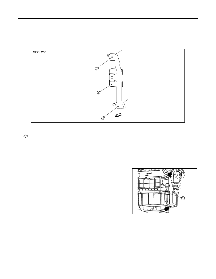
POWER STEERING CONTROL UNIT
Exploded View
INFOID:0000000003131130
Removal and Installation
INFOID:0000000003131131
REMOVAL
1.
Remove glove box assembly. Refer to
.
2.
Remove instrument assist lower panel. Refer to
3.
Remove power steering control unit screws.
4.
Remove power steering control unit (1).
5.
Disconnect power steering control unit connector.
INSTALLATION
Install in the reverse order of removal.
1.
Power steering control unit
: Vehicle front
JSGIA0129ZZ
JSGIA0130ZZ
STR-1
ENGINE
C
D
E
F
G
H
I
J
K
L
M
SECTION
STR
A
STR
N
O
P
CONTENTS
STARTING SYSTEM
BASIC INSPECTION . . . . . . . . .
DIAGNOSIS AND REPAIR WORKFLOW . . ..
Work Flow . . . . . . . . . . . . . . . .....
FUNCTION DIAGNOSIS . . . . . . . ...
STARTING SYSTEM . . . . . . . . . . ...
System Diagram . . . . . . . . . . . . . ....
System Description . . . . . . . . . . . . ...
Component Parts Location . . . . . . . . . ....
Component Description . . . . . . . . . . ....
COMPONENT DIAGNOSIS . . . . . . ..
B TERMINAL CIRCUIT . . . . . . . . . ...
Description . . . . . . . . . . . . . . . ....
Diagnosis Procedure . . . . . . . . . . . .....
S CONNECTOR CIRCUIT . . . . . . . . ...
Description . . . . . . . . . . . . . . . ....
Diagnosis Procedure . . . . . . . . . . . .....
STARTING SYSTEM . . . . . . . . . . ...
Wiring Diagram - STARTING SYSTEM - . . . . ..
SYMPTOM DIAGNOSIS . . . . . . . ..
STARTING SYSTEM . . . . . . . . . . ..
Symptom Table . . . . . . . . . . . . . ...
PRECAUTION . . . . . . . . . . . ..
PRECAUTIONS . . . . . . . . . . . . .
PREPARATION . . . . . . . . . . ...
PREPARATION . . . . . . . . . . . . .
Special Service Tools . . . . . . . . . . . ..
Commercial Service Tools . . . . . . . . . ...
ON-VEHICLE REPAIR . . . . . . . . .
STARTER MOTOR . . . . . . . . . . ...
Exploded View . . . . . . . . . . . . . . .
Removal and Installation . . . . . . . . . . .
Inspection . . . . . . . . . . . . . . . .
SERVICE DATA AND SPECIFICATIONS
(SDS) . . . . . . . . . . . . . . .
SERVICE DATA AND SPECIFICATIONS
(SDS) . . . . . . . . . . . . . . . . .
Нет комментариевНе стесняйтесь поделиться с нами вашим ценным мнением.
Текст