Infiniti EX35. Manual — part 1445
TM-168
< ON-VEHICLE REPAIR >
[5AT: RE5R05A]
A/T FLUID TEMPERATURE SENSOR 2
A/T FLUID TEMPERATURE SENSOR 2
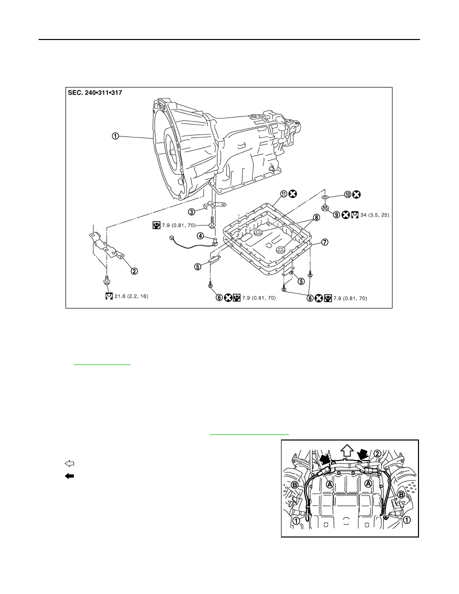
Exploded View
INFOID:0000000003130614
Removal and Installation
INFOID:0000000003130615
REMOVAL
1.
Disconnect the battery cable from the negative terminal.
2.
Drain ATF through drain plug.
3.
Remove exhaust mounting bracket. Refer to
4.
Disconnect heated oxygen sensor 2 harness connectors (A).
5.
Remove heated oxygen sensor 2 harness (B) from clips (1).
6.
Remove bracket (2) from transmission assembly.
1.
A/T
2.
Bracket
3.
Bracket
4.
A/T fluid temperature sensor 2
5.
Clip
6.
Oil pan mounting bolt
7.
Oil pan
8.
Magnet
9.
Drain plug
10. Drain plug gasket
11.
Oil pan gasket
Refer to
for symbols in the figure.
JSDIA0123GB
: Vehicle front
: Bolt
SCIA8269E

A/T FLUID TEMPERATURE SENSOR 2
TM-169
< ON-VEHICLE REPAIR >
[5AT: RE5R05A]
C
E
F
G
H
I
J
K
L
M
A
B
TM
N
O
P
7.
Remove clips (1).
8.
Remove oil pan (2) and oil pan gasket.
9.
Remove magnets (1) from oil pan.
10. Disconnect A/T fluid temperature sensor 2 connector (A).
CAUTION:
Be careful not to damage connector.
11. Disengage terminal clip (
).
12. Remove A/T fluid temperature sensor 2 (1) with bracket (2) from
control valve with TCM.
13. Remove bracket (1) from A/T fluid temperature sensor 2 (2).
3
: Drain plug
: Vehicle front
: Oil pan mounting bolt
SCIA8117E
JPDIA0009ZZ
SCIA8125E
: Bolt
JPDIA0025ZZ
JPDIA0014ZZ

TM-170
< ON-VEHICLE REPAIR >
[5AT: RE5R05A]
A/T FLUID TEMPERATURE SENSOR 2
INSTALLATION
Note the following, and install in the reverse order of removal.
CAUTION:
• Be careful not to damage connector.
• Do not reuse drain plug gasket.
• Adjust bolt hole of bracket to bolt hole of control valve with TCM when installing A/T fluid tempera-
ture sensor 2 (with bracket).
• Refer to the following when installing oil pan (2) (with oil pan gas-
ket) and clips (1) to transmission case.
CAUTION:
• Do not reuse oil pan gasket and oil pan mounting bolts.
• Install oil pan gasket in the direction to align hole position.
• Install it so that drain plug (3) comes to the position as
shown in the figure.
• Be careful not to pinch harnesses.
• Completely remove all moisture, oil and old gasket, etc. from oil pan mounting surface.
- Tighten oil pan mounting bolts to the specified torque in numerical
order shown in the figure after temporarily tightening them. Tighten
oil pan mounting bolts to the specified torque.
Inspection
INFOID:0000000003130616
INSPECTION AFTER REMOVAL
Check foreign materials in oil pan to help determine causes of mal-
function. If the ATF is very dark, smells burned, or contains foreign
particles, the frictional material (clutches, band) may need replace-
ment. A tacky film that will not wipe clean indicates varnish build up.
Varnish can cause valves, servo, and clutches to stick and can
inhibit pump pressure.
• If frictional material is detected, perform A/T fluid cooler
cleaning. Refer to
.
INSPECTION AFTER INSTALLATION
Check for A/T fluid leakage and A/T fluid level after completing installation. Refer to
: Vehicle front
: Oil pan mounting bolt
: Vehicle front
SCIA8117E
JPDIA0021ZZ
SCIA5199E
PARKING COMPONENTS
TM-171
< ON-VEHICLE REPAIR >
[5AT: RE5R05A]
C
E
F
G
H
I
J
K
L
M
A
B
TM
N
O
P
PARKING COMPONENTS
2WD
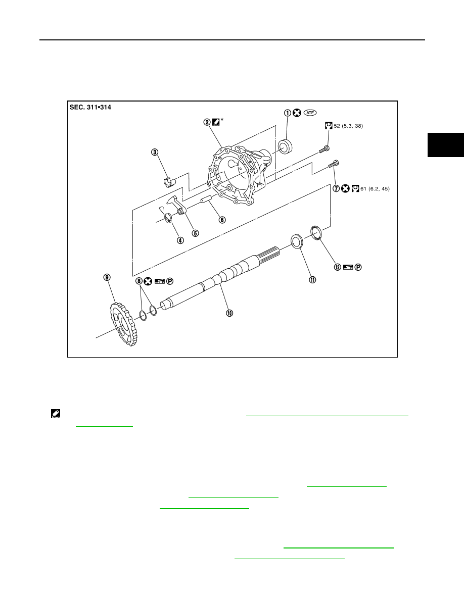
2WD : Exploded View
INFOID:0000000003130617
2WD : Removal and Installation
INFOID:0000000003130618
REMOVAL
1.
Drain ATF through drain plug.
2.
Remove exhaust front tube and center muffler with power tool. Refer to
.
3.
Remove rear propeller shaft. Refer to
4.
Remove control rod. Refer to
.
5.
Support A/T assembly with a transmission jack.
CAUTION:
When setting transmission jack, be careful not to allow it to collide against the drain plug.
6.
Remove rear engine mounting member with power tool. Refer to
7.
Remove engine mounting insulator (rear). Refer to
1.
Rear oil seal
2.
Rear extension
3.
Parking actuator support
4.
Return spring
5.
Parking pawl
6.
Pawl shaft
7.
Self-sealing bolt
8.
Seal ring
9.
Parking gear
10.
Output shaft
11.
Bearing race
12. Needle bearing
*
: Apply Genuine Anaerobic Liquid Gasket or equivalent. Refer to
GI-15, "Recommended Chemical Products and Sealants"
.
Refer to
for symbols not described on the above.
SCIA8364E
Нет комментариевНе стесняйтесь поделиться с нами вашим ценным мнением.
Текст