Infiniti EX35. Manual — part 550
DLN-150
< ON-VEHICLE REPAIR >
[REAR FINAL DRIVE: R200]
FRONT OIL SEAL
AWD : Removal and Installation
INFOID:0000000003135822
REMOVAL
CAUTION:
Verify identification stamp of replacement frequency put in the lower part of gear carrier to determine
replacement for collapsible spacer when replacing front oil seal. Refer to “Identification stamp of
replacement frequency of front oil seal”. If collapsible spacer replacement is necessary, remove final
drive assembly and disassemble it to replace front oil seal and collapsible spacer. Refer to
"AWD : Removal and Installation"
and
NOTE:
The reuse of collapsible spacer is prohibited in principle. However, it is reusable on a one-time basis
only in cases when replacing front oil seal.
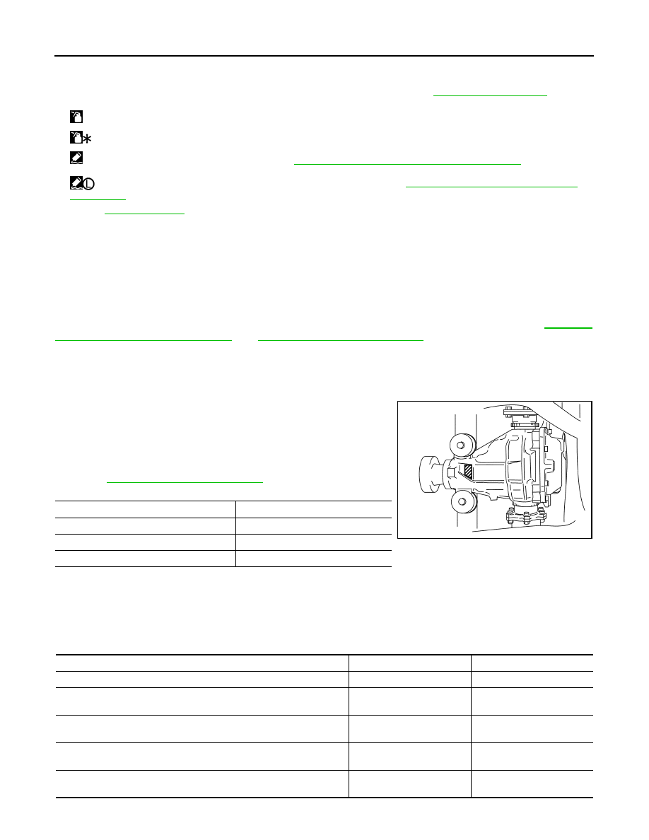
Identification stamp of replacement frequency of front oil seal
• The diagonally shaded area in the figure shows stamping point for
replacement frequency of front oil seal.
• The following table shows if collapsible spacer replacement is
needed before replacing front oil seal.
When collapsible spacer replacement is required, disassemble
final drive assembly to replace collapsible spacer and front oil seal.
Refer to
.
CAUTION:
Make a stamping after replacing front oil seal.
• After replacing front oil seal, make a stamping on the stamping point in accordance with the table below in
order to identify replacement frequency.
CAUTION:
Make a stamping from left to right.
25. Gasket
26. Rear cover
27. Drain plug
A.
Oil seal lip
B.
Screw hole
C.
For the tightening torque, refer to
.
: Apply gear oil.
: Apply anti-corrosion oil.
: Apply Genuine Silicone RTV or equivalent. Refer to
GI-15, "Recommended Chemical Products and Sealants"
.
: Apply Genuine High Strength Thread Locking Sealant or equivalent. Refer to
GI-15, "Recommended Chemical Products
Refer to
for symbols not described above.
Stamp
collapsible spacer replacement
No stamp
Not required
“0” or “0” on the far right of stamp
Required
“01” or “1” on the far right of stamp
Not required
PDIA0976E
Stamp before stamping
Stamping on the far right
Stamping
No stamp
0
0
“0”
(Front oil seal was replaced once.)
1
01
“01”
(Collapsible spacer and front oil seal were replaced last time.)
0
010
“0” is on the far right.
(Only front oil seal was replaced last time.)
1
...01
“1” is on the far right.
(Collapsible spacer and front oil seal were replaced last time.)
0
...010
FRONT OIL SEAL
DLN-151
< ON-VEHICLE REPAIR >
[REAR FINAL DRIVE: R200]
C
E
F
G
H
I
J
K
L
M
A
B
DLN
N
O
P
1.
Drain gear oil. Refer to
.
2.
Make a judgment if a collapsible spacer replacement is required.
3.
Remove center muffler with a power tool. Refer to
4.
Remove rear wheel sensor. Refer to
BRC-107, "FRONT WHEEL SENSOR : Exploded View"
5.
Remove drive shaft from final drive. Then suspend it by wire, etc. Refer to
.
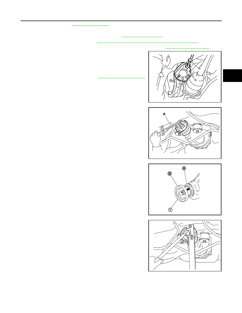
6.
Install attachment (A) [SST: KV40104100 (
—
)] to side
flange, and then pull out the side flange with the sliding hammer
(B) [SST: ST36230000 (J-25840-A)].
NOTE:
Circular clip installation position: Final drive side
7.
Remove rear propeller shaft. Refer to
8.
Measure the total preload with the preload gauge (A) [SST:
ST3127S000 (J-25765-A)].
NOTE:
Record the preload measurement.
9.
Put matching mark (B) on the end of the drive pinion. The
matching mark should be in line with the matching mark (A) on
companion flange (1).
CAUTION:
For matching mark, use paint. Never damage companion
flange and drive pinion.
NOTE:
The matching mark on the final drive companion flange indicates
the maximum vertical runout position.
10. Remove drive pinion lock nut using the flange wrench.
JSDIA0105ZZ
PDIA0977E
PDIA0750J
PDIA0978E
DLN-152
< ON-VEHICLE REPAIR >
[REAR FINAL DRIVE: R200]
FRONT OIL SEAL
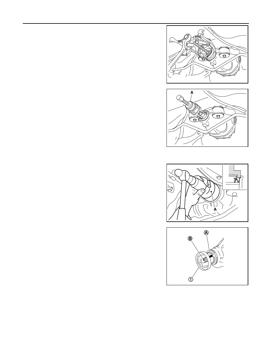
11. Remove companion flange using pullers.
12. Remove front oil seal using the puller (A) [SST: KV381054S0 (J-
34286)].
INSTALLATION
1.
Apply multi-purpose grease to front oil seal lips.
2.
Install front oil seal using the drift (A) [SST: ST30720000 (J-
25405)] as shown in figure.
CAUTION:
• Never reuse oil seal.
• Never incline oil seal when installing.
3.
Align the matching mark (B) of drive pinion with the matching
mark (A) of companion flange (1), and then install the compan-
ion flange.
PDIA0979E
PDIA0980E
PDIA0752J
PDIA0750J
FRONT OIL SEAL
DLN-153
< ON-VEHICLE REPAIR >
[REAR FINAL DRIVE: R200]
C
E
F
G
H
I
J
K
L
M
A
B
DLN
N
O
P
4.
Apply anti-corrosion oil to the thread and seat of new drive pin-
ion lock nut, and temporarily tighten drive pinion lock nut to drive
pinion.
CAUTION:
Never reuse drive pinion lock nut.
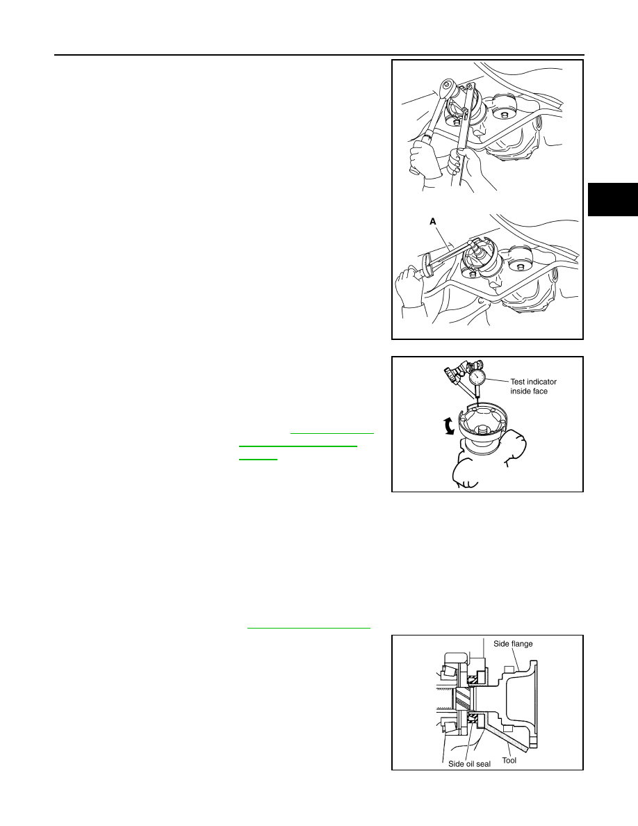
5.
Tighten drive pinion lock nut within the limits of specified torque
so as to keep the pinion bearing preload within a standard val-
ues.
CAUTION:
• Adjust to the lower limit of the drive pinion lock nut tight-
ening torque first.
• If the preload torque exceeds the specified value, replace
collapsible spacer and tighten it again to adjust. Never
loosen drive pinion lock nut to adjust the preload torque.
6.
Fit a test indicator to the inner side of companion flange (socket
diameter).
7.
Rotate companion flange to check for runout.
• If the runout value is outside the runout limit, follow the proce-
dure below to adjust.
- Check for runout while changing the phase between compan-
ion flange and drive pinion by 90
°
step, and search for the position where the runout is the minimum.
- If the runout value is still outside of the limit after the phase has been changed, possible cause will be an
assembly malfunction of drive pinion and pinion bearing and malfunction of pinion bearing. Check for
these items and repair if necessary.
- If the runout value is still outside of the limit after the check and repair, replace companion flange.
8.
Make a stamping for identification of front oil seal replacement frequency. Refer to “Identification stamp of
replacement frequency of front oil seal”.
CAUTION:
Make a stamping after replacing front oil seal.
9.
Install rear propeller shaft. Refer to
.
10. Install side flange with the following procedure.
a.
Attach the protector [SST: KV38107900 (J-39352)] to side oil
seal.
b.
After the side flange is inserted and the serrated part of side
gear has engaged the serrated part of flange, remove the pro-
tector.
c.
Put a suitable drift on the center of side flange, then drive it until
sound changes.
NOTE:
When installation is completed, driving sound of the side flange
turns into a sound that seems to affect the whole final drive.
A
: Preload gauge [SST: ST3127S000 (J-25765-A)]
Standard
Total preload torque
: A value that add 0.1 – 0.4
N·m (0.01 – 0.04 kg-m) to
the measured value when
removing.
PDIA0981E
Limit
Companion flange runout
: Refer to
PDIA0490E
SDIA0822E
Нет комментариевНе стесняйтесь поделиться с нами вашим ценным мнением.
Текст