Infiniti EX35. Manual — part 177
AV
DIAGNOSIS SYSTEM (AV CONTROL UNIT)
AV-489
< FUNCTION DIAGNOSIS >
[BOSE AUDIO WITH NAVIGATION]
C
D
E
F
G
H
I
J
K
L
M
B
A
O
P
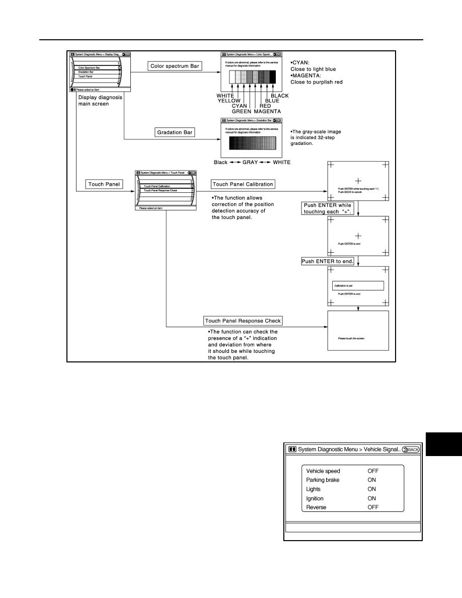
Display Diagnosis
The tint of the color bar indication is as per the following list if a RGB signal error is detected.
Vehicle Signals
A comparison check can be made of each actual vehicle signal and
the signals recognized by the system.
JSNIA0689GB
R (red) signal error
: Light blue (Cyan) tint
G (green) signal error
: Purple (Magenta) tint
B (blue) signal error
: Yellow tint
JSNIA0075GB
AV-490
< FUNCTION DIAGNOSIS >
[BOSE AUDIO WITH NAVIGATION]
DIAGNOSIS SYSTEM (AV CONTROL UNIT)
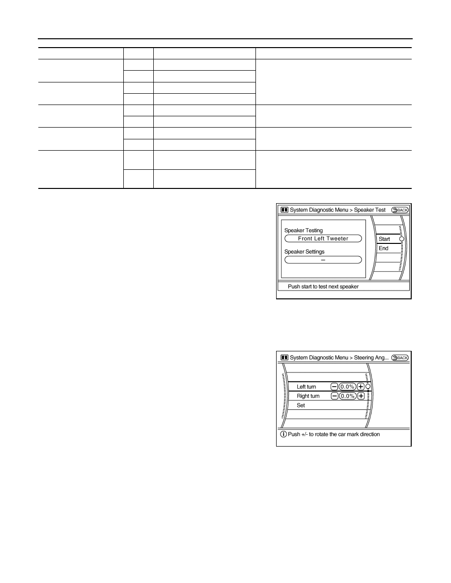
Speaker Test
Select “SPEAKER DIAGNOSIS” to display the Speaker Diagnosis
screen. Press “START and NEXT” to generate a test tone in a
speaker. Press “Start” to generate a test tone in the next speaker.
Press “End” to stop the test tones.
NOTE:
The frequency of test tone emitted from each speaker is as follows.
*: Squawker
Climate Control
Refer to “HEATER & AIR CONDITIONING CONTROL SYSTEM” for details.
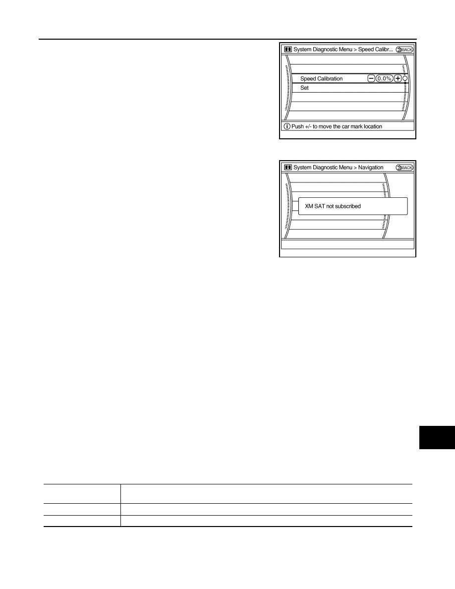
Navigation
STEERING ANGLE ADJUSTMENT
The steering angle output value detected with the gyroscope is
adjusted.
SPEED CALIBRATION
Diagnosis item
Display
Vehicle status
Remarks
Vehicle speed
ON
Vehicle speed > 0 km/h (0 MPH)
Changes in indication may be delayed. This is normal.
OFF
Vehicle speed = 0 km/h (0 MPH)
Parking brake
ON
Parking brake is applied.
OFF
Parking brake is released.
Lights
ON
Light switch ON
—
OFF
Light switch OFF
Ignition
ON
Ignition switch ON
—
OFF
Ignition switch in THE ACC position
Reverse
ON
Shift the selector lever to the “R”
position
Changes in indication may be delayed. This is normal.
OFF
Shift the selector lever to a position
other than the “R” position
Tweeter*
: 3 kHz
Front speaker
: 300 Hz
Rear speaker
: 1 kHz
JSNIA0076GB
JSNIA0077GB
AV
DIAGNOSIS SYSTEM (AV CONTROL UNIT)
AV-491
< FUNCTION DIAGNOSIS >
[BOSE AUDIO WITH NAVIGATION]
C
D
E
F
G
H
I
J
K
L
M
B
A
O
P
During normal driving, distance error caused by tire wear and tire
pressure change is automatically adjusted for by the automatic dis-
tance correction function. This function, on the other hand, is for
immediate adjustment, in cases such as driving with tire chains fitted
on tires.
XM SAT SUBSCRIPTION STATUS
The XM NavTraffic subscription status can be checked.
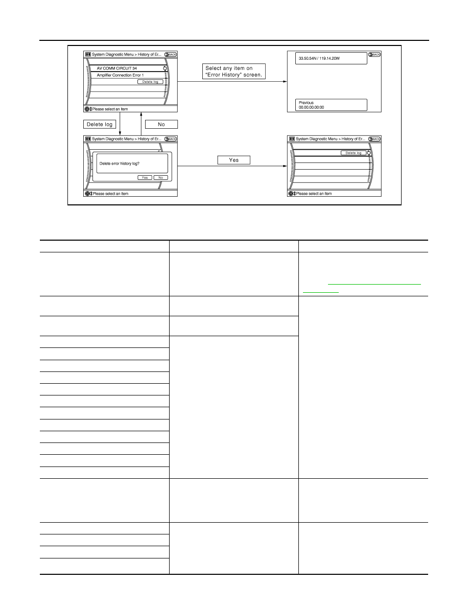
Error History
The self-diagnosis results are judged depending on whether any error occurs from when “Self-diagnosis” is
selected until the self-diagnosis results are displayed.
However, the diagnosis results are judged normal if an error has occurred before the ignition SW is turned ON
and then no error has occurred until the self-diagnosis start. Check the “Error Record” to detect any error that
may have occurred before the self-diagnosis start because of this condition.
The error record displays the time and place of the most recent occurrence of that error. However, take note of
the following points.
• If there is a malfunction with the GPS antenna circuit board in AV control unit, the correct date and time of
occurrence may not be displayed.
• Place of the error occurrence is represented by the position of the current location mark at the time an error
occurred. If current location mark has deviated from the correct position, then the place of the error occur-
rence cannot be located correctly.
• The frequency of occurrence is displayed in a count up manner. The actual count up method differs depend-
ing on the error item.
Count up method A
• The counter resets to 0 if an error occurs when IGN switch is turned ON. The counter increases by 1 if the
condition is normal at a next IGN ON cycle.
• The counter upper limit is 39. Any counts exceeding 39 are ignored. The counter can be reset (no error
record display) with the “Delete log” switch or CONSULT-III.
Count up method B
• The counter increases by 1 if an error occurs when IGN switch is ON. The counter will not decrease even if
the condition is normal at the next IGN ON cycle.
• The counter upper limit is 50. Any counts exceeding 50 are ignored. The counter can be reset (no error
record display) with the “Delete log” switch or CONSULT-III.
JSNIA0078GB
JSNIA0089GB
Display type of occur-
rence frequency
Error history display item
Count up method A
CAN communication line, control unit (CAN), AV communication line, control unit (AV communication)
Count up method B
Other than the above
AV-492
< FUNCTION DIAGNOSIS >
[BOSE AUDIO WITH NAVIGATION]
DIAGNOSIS SYSTEM (AV CONTROL UNIT)
Error item
Some error items may be displayed simultaneously according to the cause. If some error items are displayed
simultaneously, the detection of the cause can be performed by the combination of display items.
JSNIA0079GB
Error item
Detection logic
Possible malfunction factor/Action to take
CAN COMM CIRCUIT
CAN communication malfunction is detect-
ed.
Perform diagnosis with CONSULT-III, and
then repair the malfunctioning parts accord-
ing to the diagnosis results.
Refer to
CONTROL UNIT (CAN)
CAN initial diagnosis malfunction is detect-
ed.
Replace AV control unit.
CONTROL UNIT (AV)
AV communication circuit initial diagnosis
malfunction is detected.
FLASH-ROM Error Of Control Unit
AV control unit malfunction is detected.
Connection Of Gyro
XM SERIAL COMM Error
CAN Controller Memory Error
Bluetooth Module Connection Error
HDD CONN Error
HDD READ Error
HDD WRITE Error
HDD COMM Error
HDD ACCESS Error
DSP CONN Error
DSP COMM Error
Internal Communication Error
When either one of the following items
are detected:
• Malfunction is detected in AV control unit
power supply or ground circuits.
• AV control unit malfunction is detected.
• AV control unit power supply and ground
circuits.
• When there is no malfunction, AV control
unit is malfunctioning.
GPS Communication Error
GPS malfunction is detected.
An intermittent error caused by strong radio
interference may be detected unless any
symptom (GPS reception error, etc.) oc-
curs.
Replace AV control unit if the malfunction
occurs constantly.
GPS ROM Error
GPS RAM Error
GPS RTC Error
Нет комментариевНе стесняйтесь поделиться с нами вашим ценным мнением.
Текст