Infiniti EX35. Manual — part 101
AV
HANDS-FREE PHONE SYSTEM
AV-185
< FUNCTION DIAGNOSIS >
[BOSE AUDIO WITHOUT NAVIGATION]
C
D
E
F
G
H
I
J
K
L
M
B
A
O
P
HANDS-FREE PHONE SYSTEM
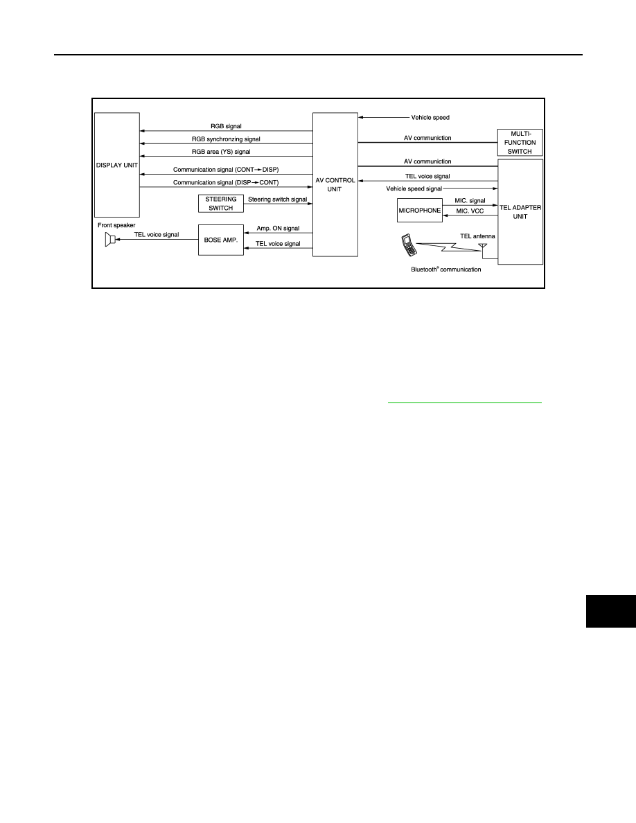
System Diagram
INFOID:0000000003508658
System Description
INFOID:0000000003508659
• TEL adapter unit is controlled with AV communication from AV control unit.
• The connection between portable telephone and TEL adapter unit is performed via Bluetooth
®
communica-
tion.
• The voice guidance signal is input from TEL adapter unit to AV control unit and output via BOSE amp. to
front speaker when operating TEL.
• TEL adapter unit has the on board self-diagnosis function. Refer to
AV-205, "Diagnosis Description"
When receiving a call
TEL voice signal received with the portable telephone is input from TEL antenna via TEL adapter unit to AV
control unit via Bluetooth
®
communication and output via BOSE amp. to front speaker. The operation is per-
formed via steering switch or voice recognition function (TEL operation only).
When a call is transmitted
Voice sound (TEL voice signal) is input from the microphone to TEL adapter unit. It is input from TEL antenna
via Bluetooth communication to portable telephone. It is transmitted to phone on the other side. The operation
is performed with steering switch or voice recognition function (TEL operation only).
JSNIA0701GB
AV-186
< FUNCTION DIAGNOSIS >
[BOSE AUDIO WITHOUT NAVIGATION]
HANDS-FREE PHONE SYSTEM
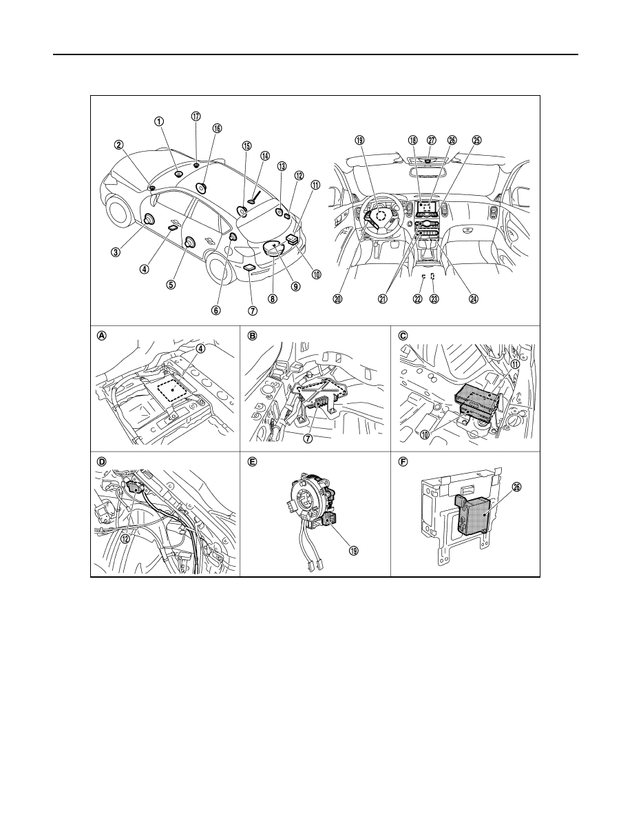
Component Parts Location
INFOID:0000000003579814
1.
Center speaker
2.
Front squawker LH
3.
Front door speaker LH
4.
Camera control unit
5.
Rear door speaker LH
6.
Rear squawker LH
7.
BOSE amp.
8.
Woofer
9.
Rear view camera
10. Satellite radio tuner
11. TEL adapter unit
12. TEL antenna
13. Rear squawker RH
14. Antenna base (antenna amp and sat-
ellite antenna)
15. Rear door speaker RH
16. Front door speaker RH
17. Front squawker RH
18. Display unit
19. Steering angle sensor
20. Steering switch
21. Preset switch
22. iPod connector
23. Auxiliary input jacks
24. AV control unit
25. Multifunction switch
26. iPod adapter
27. Microphone
A.
Under front seat (LH side)
B.
Luggage floor (LH side)
C.
Luggage floor (RH side)
D.
Luggage side RH
E.
Spiral cable part
F.
Rear view of the display unit
JPNIA0910ZZ

AV
HANDS-FREE PHONE SYSTEM
AV-187
< FUNCTION DIAGNOSIS >
[BOSE AUDIO WITHOUT NAVIGATION]
C
D
E
F
G
H
I
J
K
L
M
B
A
O
P
Component Description
INFOID:0000000003508661
Part name
Description
AV CONTROL UNIT
• Inputs TEL voice signal or voice guidance signal from TEL adapter unit and
outputs it to BOSE amp. during reception.
• Connects with TEL adapter unit and AV communication and controls hands
free phone system.
DISPLAY UNIT
• Display image is controlled by the serial communication from AV control unit.
• Inputs RGB image signal (RGB, RGB area and RGB synchronizing) from AV
control unit and displays the status of hands free phone system.
BOSE AMP.
Inputs TEL voice signal or voice guidance signal from AV control unit and outputs
it to front speaker and center speaker.
FRONT DOOR SPEAKER
Outputs TEL voice signal or voice guidance signal from BOSE amp.
FRONT SQUAWKER
PRESET SWITCH
• Adjust the sound when using TEL.
• The operation signal is transmitted to AV control unit via AV communication.
STEERING SWITCH
• The hands free phone system can be operated.
• Steering switch signal (operation signal) is output to AV control unit.
MICROPHONE
• Used when operating the hands-free phone.
• Outputs Mic. signal (TEL voice signal) to TEL adapter unit.
• The power (Mic. power supply) is supplied from TEL adapter unit.
TEL ADAPTER UNIT
• Receives the steering switch signal (operation signal) from steering switch.
• Inputs the TEL voice signal from TEL antenna during reception and outputs it
to AV control unit.
• Inputs TEL voice signal from microphone during speech recognition and out-
puts it to TEL antenna.
• Controlled by AV communication transmitted from AV control unit.
TEL ANTENNA
Connects with the portable telephone via Bluetooth
®
communication and trans-
mits TEL voice signal.
AV-188
< FUNCTION DIAGNOSIS >
[BOSE AUDIO WITHOUT NAVIGATION]
REAR VIEW MONITOR SYSTEM
REAR VIEW MONITOR SYSTEM
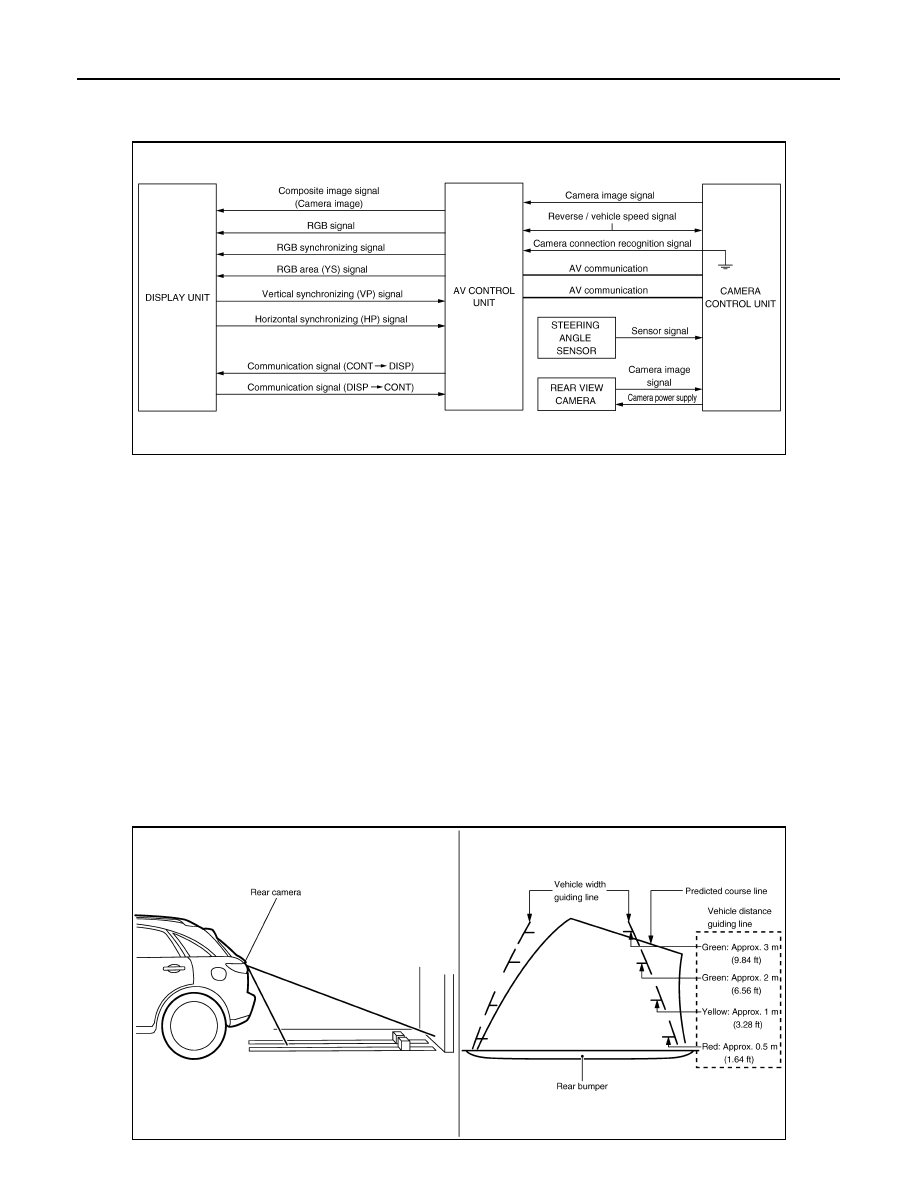
System Diagram
INFOID:0000000003161227
System Description
INFOID:0000000003161228
CAMERA IMAGE OPERATION PRINCIPLE
• Power is supplied to rear view camera from camera control unit and the rear view camera outputs the cam-
era image to camera control unit when selector lever is set to reverse position and the reverse signal on
camera control unit is input.
• Camera control unit superimposes the guiding line and predicted course line to the image from rear view
camera and outputs to display unit. In this case, the reverse signal is also input to AV control unit. Therefore,
AV control unit recognizes the selector lever as in the reverse position. And then AV control unit switches the
image displayed by the communication signal between AV control unit and display unit with the camera
image.
• AV control unit outputs camera image signal that is inputted from camera control unit to display unit.
• Camera control unit controls the direction and distance of predicted course line according to the sensor sig-
nal from steering angle sensor.
• AV control unit determines whether rear view camera is equipped or not, based on the presence of camera
connection recognition signal. It switches to rear view monitor image at the time of reverse signal input when
rear view camera is equipped.
• Warning message under the rear view monitor display is described by AV control unit.
Rear view monitor guiding line
JSNIA0698GB
JSNIA0707GB
Нет комментариевНе стесняйтесь поделиться с нами вашим ценным мнением.
Текст