Infiniti EX35. Manual — part 553
DLN-162
< REMOVAL AND INSTALLATION >
[REAR FINAL DRIVE: R200]
REAR FINAL DRIVE ASSEMBLY
1.
Remove center muffler with a power tool. Refer to
2.
Remove stabilizer bar with a power tool. Refer to
.
3.
Remove rear propeller shaft from the final drive. Refer to
.
4.
Remove drive shaft from final drive with a power tool. Then sus-
pend it by wire, etc. Refer to
5.
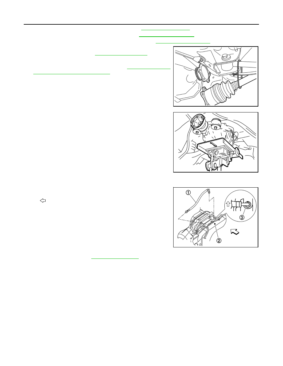
Remove breather hose from the final drive.
6.
Remove rear wheel sensor. Refer to
7.
Set a suitable jack to rear final drive assembly.
CAUTION:
Never place a jack on the rear cover (aluminum case).
8.
Remove the mounting bolts and nuts connecting to the suspen-
sion member, and remove rear final drive assembly with a power
tool.
CAUTION:
Secure rear final drive assembly to a suitable jack while
removing it.
INSTALLATION
Note the following, and installation is in the reverse order of removal.
• When installing breather hose (1), refer to the figure.
CAUTION:
Make sure there are no pinched or restricted areas on the
breather hose caused by bending or winding when installing
it.
- Insert the resin connector into rear suspension member (2). Install
the metal connector (3) in rear cover so that a paint mark becomes
forward of the vehicle as shown in the figure. Arrange the breather
hose then to pass by over wheel sensor harness.
• When oil leaks while removing final drive assembly, check oil level
after the installation. Refer to
SDIA1094E
JSDIA0131ZZ
: Vehicle front
PDIA0754E
DIFFERENTIAL ASSEMBLY
DLN-163
< DISASSEMBLY AND ASSEMBLY >
[REAR FINAL DRIVE: R200]
C
E
F
G
H
I
J
K
L
M
A
B
DLN
N
O
P
DISASSEMBLY AND ASSEMBLY
DIFFERENTIAL ASSEMBLY
2WD
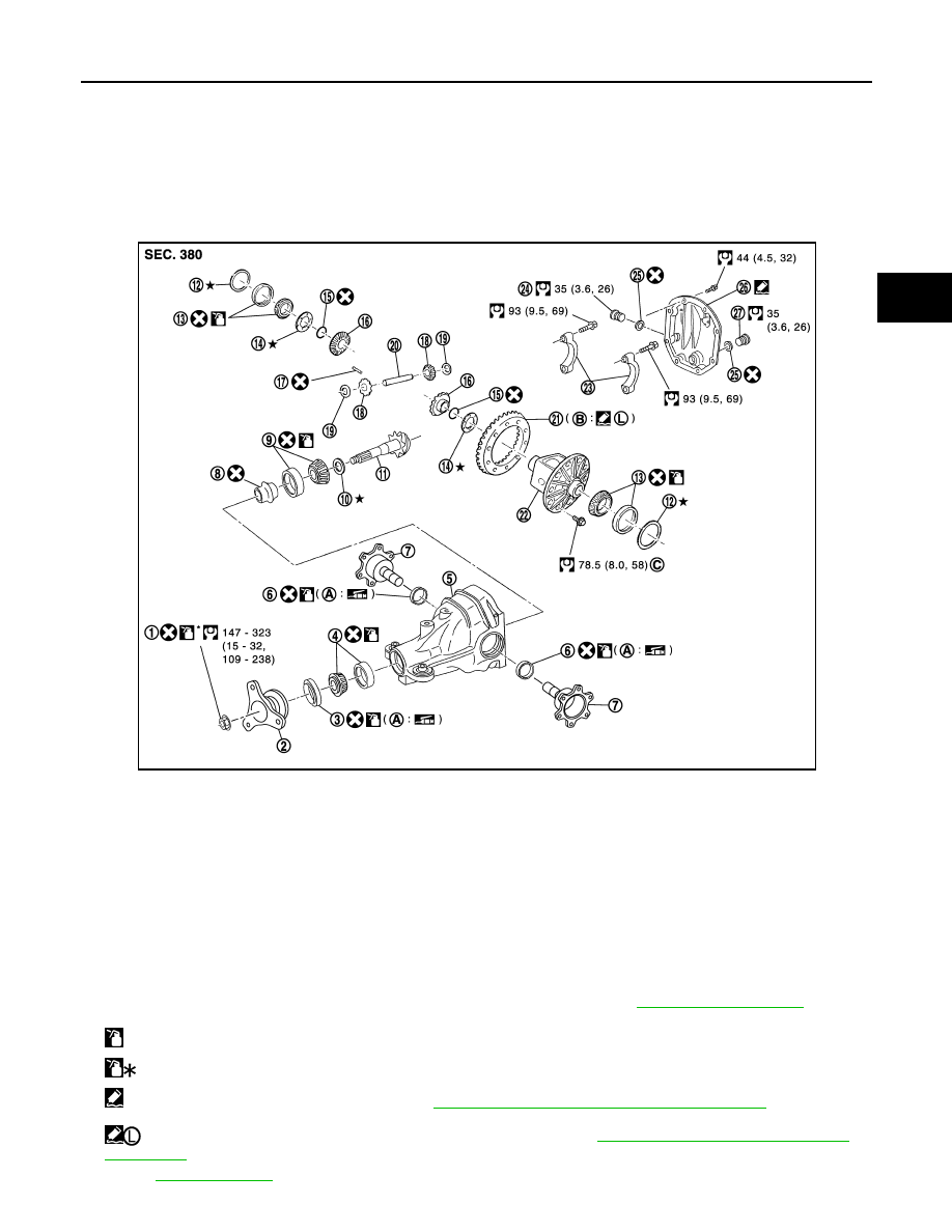
2WD : Exploded View
INFOID:0000000003135831
1.
Drive pinion lock nut
2.
Companion flange
3.
Front oil seal
4.
Pinion front bearing
5.
Gear carrier
6.
Side oil seal
7.
Side flange
8.
Collapsible spacer
9.
Pinion rear bearing
10. Pinion height adjusting washer
11.
Drive pinion
12. Side bearing adjusting washer
13. Side bearing
14. Side gear thrust washer
15. Circular clip
16. Side gear
17. Lock pin
18. Pinion mate gear
19. Pinion mate thrust washer
20. Pinion mate shaft
21. Drive gear
22. Differential case
23. Bearing cap
24. Filler plug
25. Gasket
26. Rear cover
27. Drain plug
A.
Oil seal lip
B.
Screw hole
C.
For the tightening torque, refer to
.
: Apply gear oil.
: Apply anti-corrosion oil.
: Apply Genuine Silicone RTV or equivalent. Refer to
GI-15, "Recommended Chemical Products and Sealants"
.
: Apply Genuine High Strength Thread Locking Sealant or equivalent. Refer to
GI-15, "Recommended Chemical Products
Refer to
for symbols not described above.
JPDID0129GB
DLN-164
< DISASSEMBLY AND ASSEMBLY >
[REAR FINAL DRIVE: R200]
DIFFERENTIAL ASSEMBLY
2WD : Disassembly
INFOID:0000000003135832
1.
Drain gear oil, if necessary.
2.
Remove side flange.
3.
Remove rear cover mounting bolts.
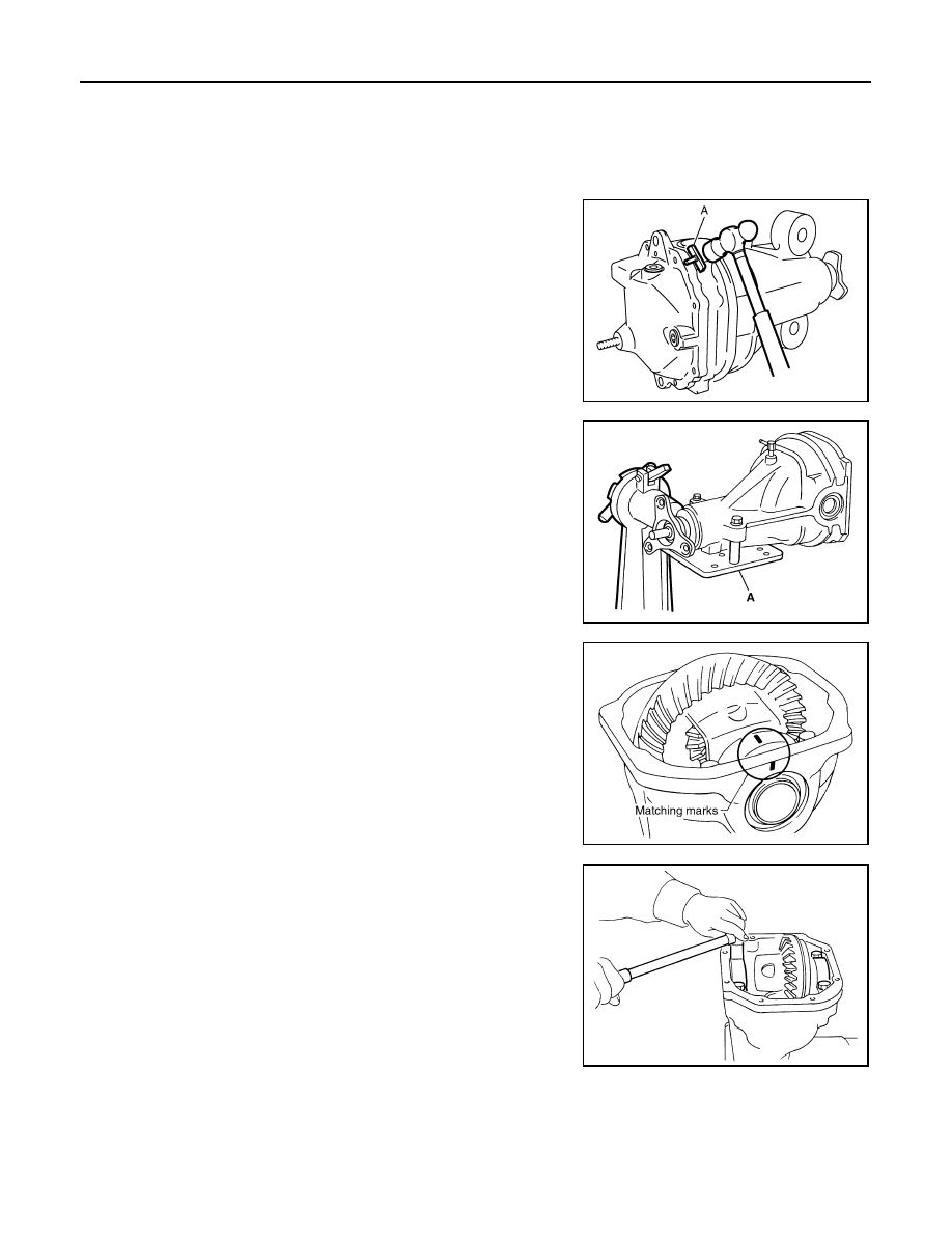
4.
Remove rear cover to insert the seal cutter (A) [SST:
KV10111100 (J-37228)] between gear carrier and rear cover.
CAUTION:
• Never damage the mating surface.
• Never insert flat-bladed screwdriver, this may damage the
mating surface.
5.
Using two 45 mm (1.77 in) spacers, mount carrier on the attach-
ment (A) [SST: KV38100800 (J-25604-01)].
6.
For proper reinstallation, paint matching marks on one side of
the bearing cap.
CAUTION:
• For matching marks, use paint. Never damage bearing
caps and gear carrier.
• Bearing caps are manufactured as integral molding. Use
the matching marks to them in their original positions.
7.
Remove bearing caps.
JSDIA0029ZZ
JSDIA0030ZZ
SDIA1795E
S-PD343
DIFFERENTIAL ASSEMBLY
DLN-165
< DISASSEMBLY AND ASSEMBLY >
[REAR FINAL DRIVE: R200]
C
E
F
G
H
I
J
K
L
M
A
B
DLN
N
O
P
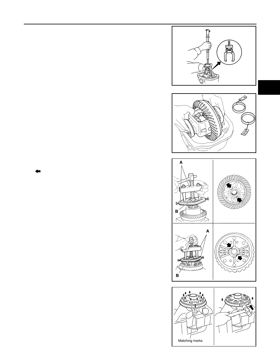
8.
Lift differential case assembly out with a suitable tool.
• Keep side bearing outer races together with inner race. Never
mix them up.
Also, keep side bearing adjusting washers together with bear-
ings.
9.
Remove side bearing inner race.
To prevent damage to bearing, engage puller jaws in groove
(
).
CAUTION:
• To prevent damage to the side bearing and drive gear,
place copper plates between these parts and vise.
• It is not necessary to remove side bearing inner race
except when it is replaced.
10. For proper reinstallation, paint matching marks on one differen-
tial case assembly.
CAUTION:
For matching marks, use paint. Never damage differential
case and drive gear.
11. Remove drive gear mounting bolts.
12. Tap drive gear off differential case assembly with a soft hammer.
CAUTION:
Tap evenly all around to keep drive gear from bending.
PDIA0547E
SPD527
A
: Puller [SST: ST33051001 (J-22888-20)]
B
: Base [SST: ST33061000 (J-8107-2)]
PDIA0758J
PDIA0496E
Нет комментариевНе стесняйтесь поделиться с нами вашим ценным мнением.
Текст