Infiniti EX35. Manual — part 552
DLN-158
< ON-VEHICLE REPAIR >
[REAR FINAL DRIVE: R200]
SIDE OIL SEAL
AWD : Removal and Installation
INFOID:0000000003135826
REMOVAL
1.
Remove center muffler with a power tool. Refer to
2.
Remove rear wheel sensor. Refer to
BRC-107, "FRONT WHEEL SENSOR : Exploded View"
3.
Remove drive shaft from final drive with a power tool. Then suspend it by wire, etc. Refer to
4.
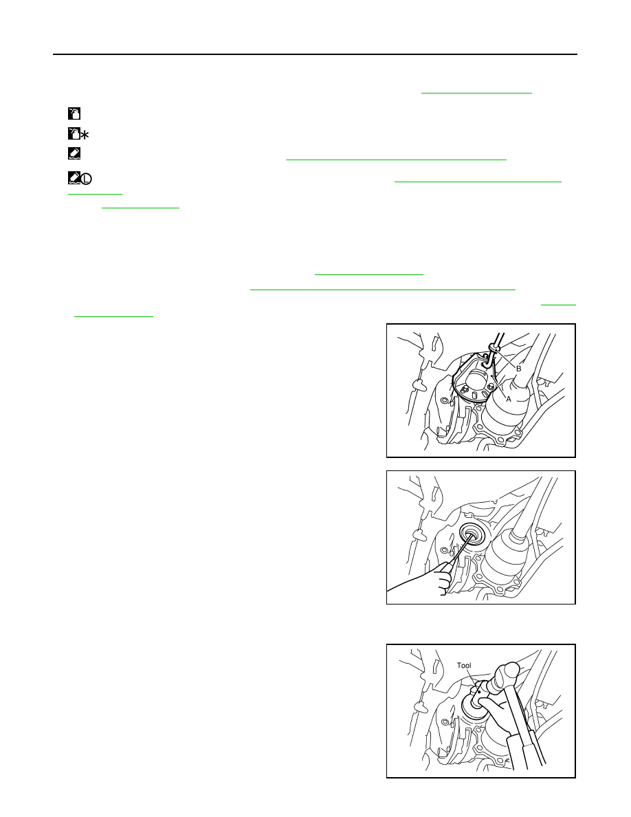
Install attachment (A) [SST: KV40104100 (
—
)] to side
flange, and then pull out the side flange with the sliding hammer
(B) [SST: ST36230000 (J-25840-A)].
NOTE:
Circular clip installation position: Final drive side
5.
Remove side oil seal, using a flat-bladed screwdriver.
CAUTION:
Never damage gear carrier.
INSTALLATION
1.
Apply multi-purpose grease to side oil seal lips.
2.
Install side oil seal until it becomes flush with the case end,
using the drift [SST: KV38100200 (J-26233)].
CAUTION:
• Never reuse oil seal.
• When installing, never incline oil seal.
25. Gasket
26. Rear cover
27. Drain plug
A.
Oil seal lip
B.
Screw hole
C.
For the tightening torque, refer to
.
: Apply gear oil.
: Apply anti-corrosion oil.
: Apply Genuine Silicone RTV or equivalent. Refer to
GI-15, "Recommended Chemical Products and Sealants"
.
: Apply Genuine High Strength Thread Locking Sealant or equivalent. Refer to
GI-15, "Recommended Chemical Products
Refer to
for symbols not described above.
JSDIA0105ZZ
SDIA1584E
SDIA1585E
SIDE OIL SEAL
DLN-159
< ON-VEHICLE REPAIR >
[REAR FINAL DRIVE: R200]
C
E
F
G
H
I
J
K
L
M
A
B
DLN
N
O
P
3.
Install side flange with the following procedure.
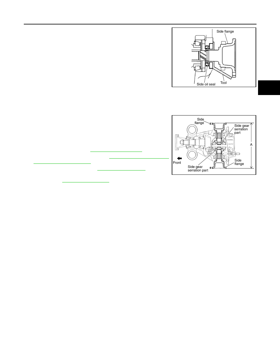
a.
Attach the protector [SST: KV38107900 (J-39352)] to side oil
seal.
b.
After the side flange is inserted and the serrated part of side
gear has engaged the serrated part of flange, remove the pro-
tector.
c.
Put a suitable drift on the center of side flange, then drive it until sound changes.
NOTE:
When installation is completed, driving sound of the side flange turns into a sound that seems to affect the
whole final drive.
d.
Confirm that the dimension of the side flange installation mea-
surement (A) in the figure comes into the following.
4.
Install drive shaft. Refer to
5.
Install rear wheel sensor. Refer to
.
6.
Install center muffler. Refer to
.
7.
When oil leaks while removing, check oil level after the installa-
tion. Refer to
.
SDIA0822E
Standard
A
: 326 – 328 mm (12.83 – 12.91 in)
SDIA1039E
DLN-160
< REMOVAL AND INSTALLATION >
[REAR FINAL DRIVE: R200]
REAR FINAL DRIVE ASSEMBLY
REMOVAL AND INSTALLATION
REAR FINAL DRIVE ASSEMBLY
2WD
2WD : Exploded View
INFOID:0000000003135827
2WD : Removal and Installation
INFOID:0000000003135828
REMOVAL
1.
Remove center muffler with a power tool. Refer to
2.
Remove stabilizer bar with a power tool. Refer to
.
3.
Remove rear propeller shaft from the final drive. Refer to
.
4.
Remove drive shaft from final drive with a power tool. Then sus-
pend it by wire, etc. Refer to
5.
Remove breather hose from the final drive.
6.
Remove rear wheel sensor. Refer to
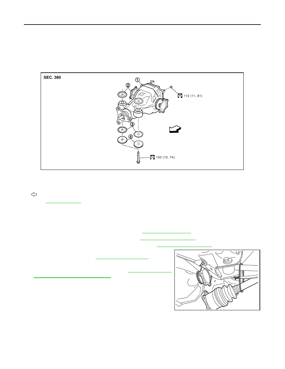
1.
Rear final drive assembly
2.
Upper stopper
3.
Lower stopper
4.
Washer
: Vehicle front
Refer to
for symbols in the figure.
JPDID0127GB
SDIA1094E
REAR FINAL DRIVE ASSEMBLY
DLN-161
< REMOVAL AND INSTALLATION >
[REAR FINAL DRIVE: R200]
C
E
F
G
H
I
J
K
L
M
A
B
DLN
N
O
P
7.
Set a suitable jack to rear final drive assembly.
CAUTION:
Never place a jack on the rear cover (aluminum case).
8.
Remove the mounting bolts and nuts connecting to the suspen-
sion member, and remove rear final drive assembly with a power
tool.
CAUTION:
Secure rear final drive assembly to a suitable jack while
removing it.
INSTALLATION
Note the following, and installation is in the reverse order of removal.
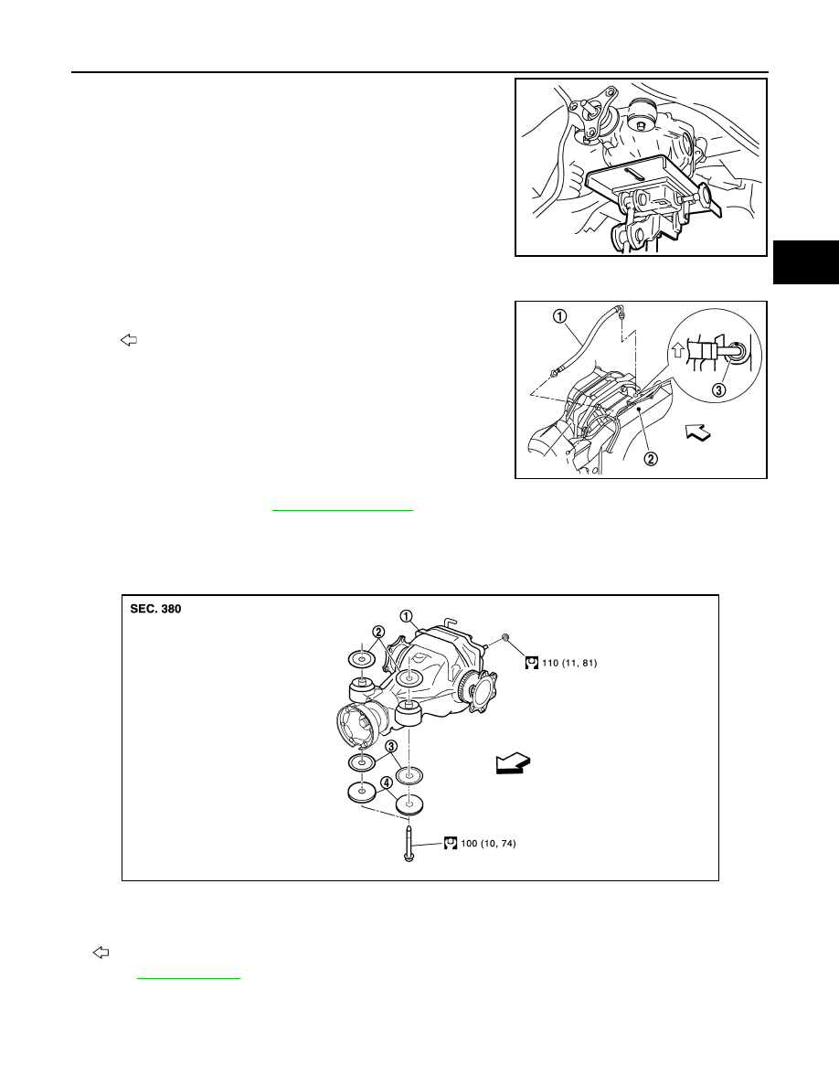
• When installing breather hose (1), refer to the figure.
CAUTION:
Make sure there are no pinched or restricted areas on the
breather hose caused by bending or winding when installing
it.
- Insert the resin connector into rear suspension member (2). Install
the metal connector (3) in rear cover so that a paint mark becomes
forward of the vehicle as shown in the figure. Arrange the breather
hose then to pass by over wheel sensor harness.
• When oil leaks while removing final drive assembly, check oil level
after the installation. Refer to
AWD
AWD : Exploded View
INFOID:0000000003135829
AWD : Removal and Installation
INFOID:0000000003135830
REMOVAL
JSDIA0026ZZ
: Vehicle front
PDIA0754E
1.
Rear final drive assembly
2.
Upper stopper
3.
Lower stopper
4.
Washer
: Vehicle front
Refer to
JPDID0203GB
Нет комментариевНе стесняйтесь поделиться с нами вашим ценным мнением.
Текст