Infiniti EX35. Manual — part 500
DLK-214
< ON-VEHICLE REPAIR >
[INTELLIGENT KEY SYSTEM]
HOOD
1.
Remove hood hinge cover (RH/LH) (1).
NOTE:
While pushing the pawls, pull hood hinge cover in the direction
of the arrow.
2.
Remove hood assembly. Refer to
DLK-211, "HOOD ASSEMBLY : Removal and Installation"
3.
Remove front fender. Refer to
DLK-219, "Removal and Installation"
4.
Remove hood hinge mounting bolts, and then remove hood hinge.
INSTALLATION
Install in the reverse order of removal.
CAUTION:
• Before installation of hood hinge, apply anticorrosive agent onto the surface of the vehicle body.
• Before installation of hood hinge, drop genuine high strength locking sealant or equivalent into bolt
hole of hood hinge (body side).
• After installation, apply touch-up paint (the body color) onto the head of the hinge mounting bolts
and nuts.
• After installation, perform hood fitting adjustment. Refer to
DLK-212, "HOOD ASSEMBLY : Adjust-
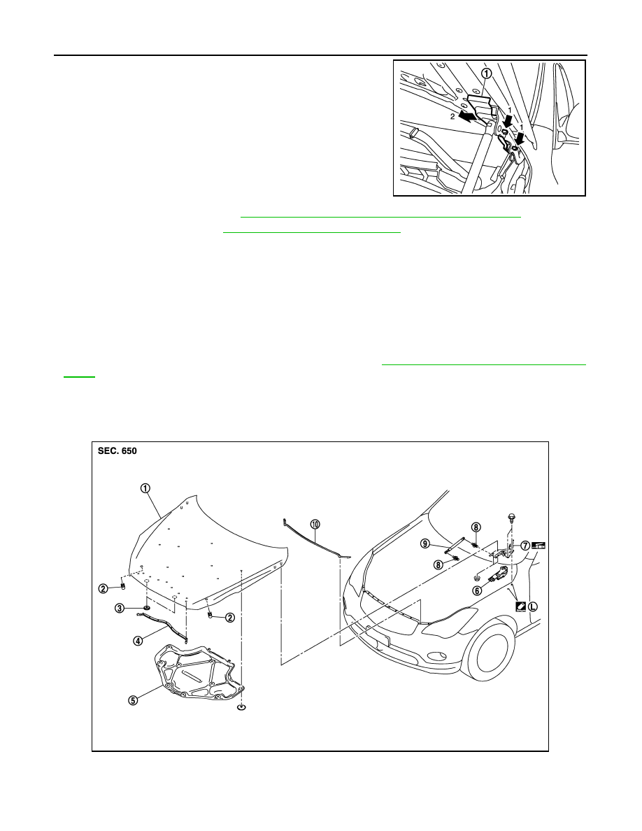
HOOD STAY
HOOD STAY : Exploded View
INFOID:0000000003586398
JMKIA2090ZZ
1.
Hood assembly
2.
Bumper rubber
3.
Seal
4.
Radiator core seal
5.
Hood insulator
6.
Hood hinge cover
JMKIA2046ZZ
HOOD
DLK-215
< ON-VEHICLE REPAIR >
[INTELLIGENT KEY SYSTEM]
C
D
E
F
G
H
I
J
L
M
A
B
DLK
N
O
P
HOOD STAY : Removal and Installation
INFOID:0000000003579491
REMOVAL
1.
Support hood lock assembly with a proper material to prevent it from falling.
WARNING:
Body injury may occur if no supporting rod is holding the hood open when removing the hood
stay.
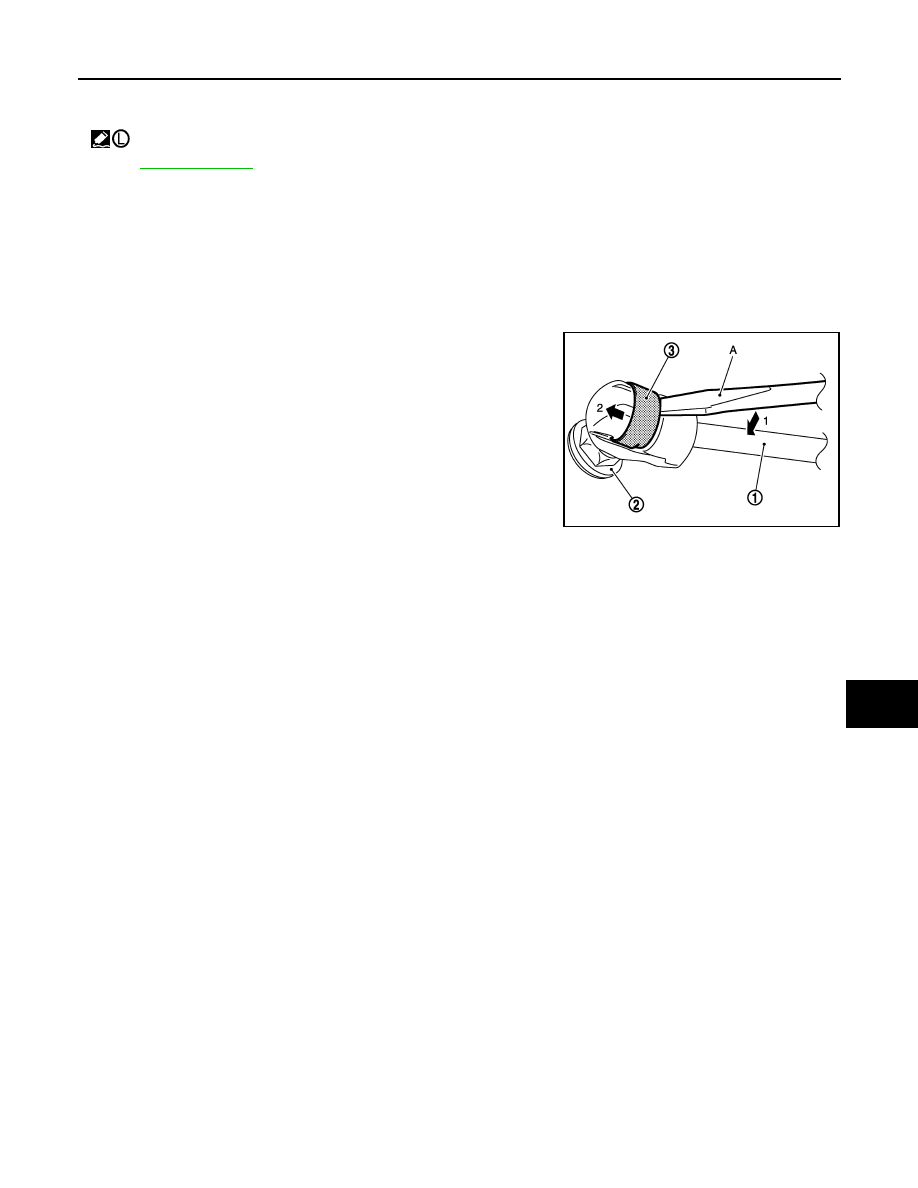
2.
Remove the metal clip (3) located on the connection between
the hood stay (1) and the stud ball (2) (hood side), by using a
flatted-blade screwdriver (A).
3.
Disengage the stud ball from the hood stay (hood side).
4.
Repeat the same operation to disengage the stud ball from the
hood stay (body side), then remove the hood stay.
INSTALLATION
Install in the reverse order of removal.
7.
Hood hinge
8.
Stud ball
9.
Hood stay
10.
Hood seal (front)
: Apply Genuine High Strength Locking Sealant or equivalent.
for symbols in the figure.
JMKIA2255ZZ
DLK-216
< ON-VEHICLE REPAIR >
[INTELLIGENT KEY SYSTEM]
RADIATOR CORE SUPPORT
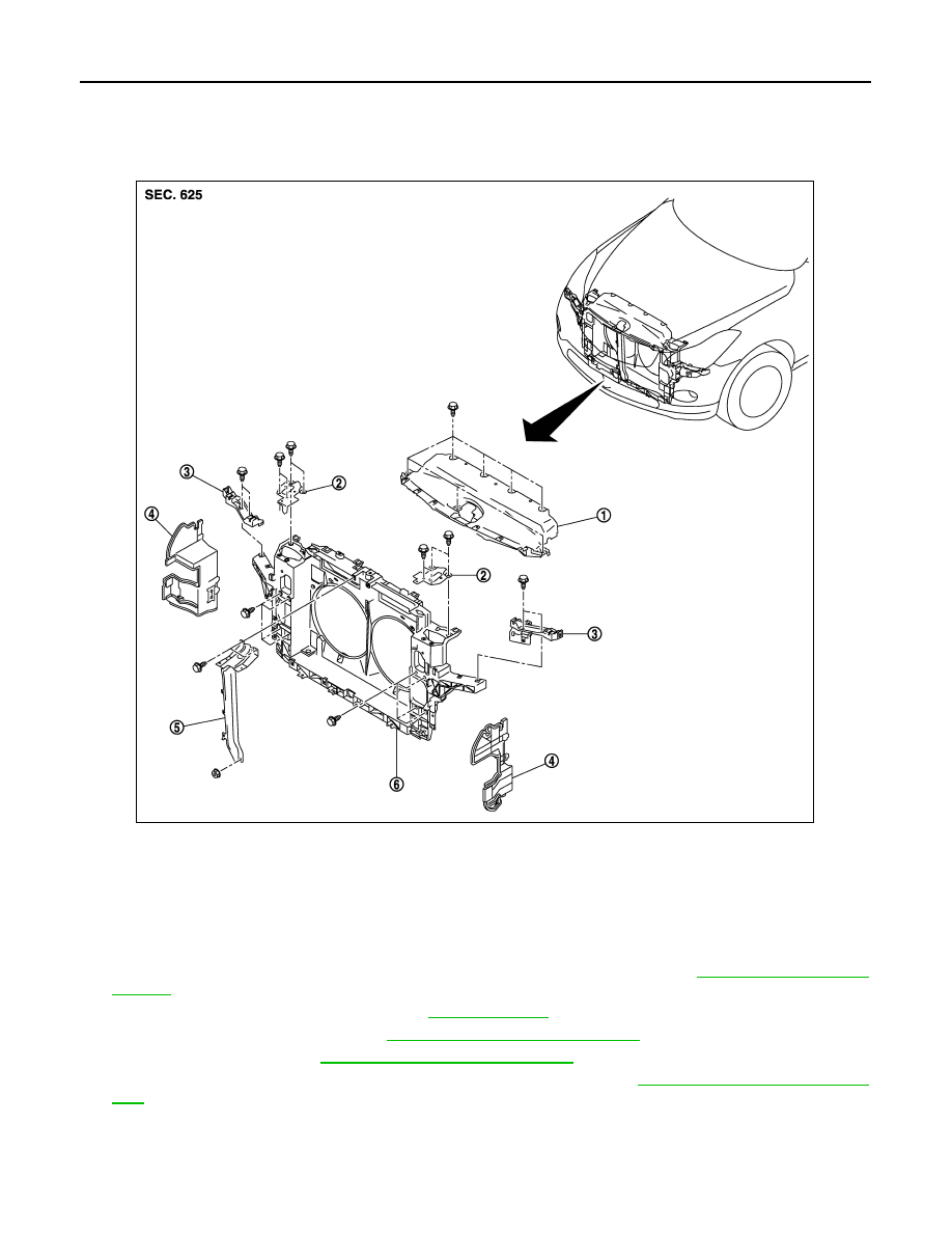
RADIATOR CORE SUPPORT
Exploded View
INFOID:0000000003556331
Removal and Installation
INFOID:0000000003556332
REMOVAL
1.
Use a refrigerant collecting equipment to discharge the refrigerant. Refer to
.
2.
Drain engine coolant from radiator. Refer to
.
3.
Remove engine under cover. Refer to
EXT-31, "Removal and Installation"
.
4.
Remove front grille. Refer to
EXT-20, "Removal and Installation"
5.
Remove front bumper fascia, energy absorber, reinforcement. Refer to
EXT-13, "Removal and Installa-
6.
Remove mounting bolts of hood lock cover.
7.
Disconnect harness clip and hood lock cable from hood lock cover.
8.
Remove hood lock cover.
1.
Hood lock cover
2.
Hood lock bracket (RH/LH)
3.
Head lamp bracket (RH/LH)
4.
Air guide (RH/LH)
5.
Hood lock stay assembly
6.
Radiator core support
JMKIA2047ZZ
RADIATOR CORE SUPPORT
DLK-217
< ON-VEHICLE REPAIR >
[INTELLIGENT KEY SYSTEM]
C
D
E
F
G
H
I
J
L
M
A
B
DLK
N
O
P
9.
Remove front combination lamp (RH/LH). Refer to
EXL-193, "Removal and Installation"
(XENON TYPE)
EXL-352, "Removal and Installation"
(HALOGEN TYPE).
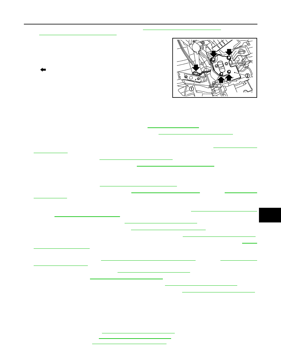
10. Disconnect hood lock switch connector (A) from head lamp
bracket (RH) (1).
11. Remove mounting bolts and remove hood lock bracket (2) (RH/
LH).
12. Disconnect hood lock cable from hood lock (RH/LH).
13. Disassembly hood lock from hood lock bracket (RH/LH).
14. Disconnect all clamp of hood cable from radiator core support assembly.
15. Disconnect harness connector of liquid tank. Refer to
.
16. Disconnect harness connector of ambient sensor. Refer to
VTL-26, "Removal and Installation"
.
17. Remove air guide (LH).
18. Remove ICC sensor integrated unit (with intelligent cruse control model). Refer to
19. Remove horn (Hi/Lo). Refer to
HRN-6, "Removal and Installation"
.
20. Remove intelligent key warning buzzer. Refer to
DLK-261, "Removal and Installation"
.
21. Disconnect harness clamp from hood lock stay.
22. Remove mounting bolt and nut, and remove hood lock stay.
23. Remove washer tank. Refer to
WW-100, "Removal and Installation"
.
24. Remove power steering oil cooler. Refer to
(2WD) or
(AWD).
25. Remove air guide (RH).
26. Remove mounting bolt of power steering oil cooler pipe bracket. Refer to
(2WD) or
(AWD).
27. Remove air cleaner box (RH/LH). Refer to
EM-27, "Removal and Installation"
.
28. Remove front under side cover (LH). Refer to
EXT-31, "Removal and Installation"
.
29. Remove radiator upper hose and lower hose at radiator side. Refer to
CO-13, "Removal and Installation"
30. Remove mounting bolts of condenser assembly from radiator core support assembly. Refer to
31. Disconnect AT fluid cooler hose (upper/lower) from fan shroud and remove AT fluid cooler hose (upper/
lower) from radiator. Refer to
TM-188, "2WD : Removal and Installation"
(2WD) or
(AWD).
32. Remove condenser assembly. Refer to
HA-53, "Removal and Installation"
33. Remove radiator. Refer to
CO-13, "Removal and Installation"
34. Disconnect harness connector of crash zone sensor. Refer to
SR-12, "Removal and Installation"
.
35. Disconnect harness connector of cooling fan control module. Refer to
CO-16, "Removal and Installation"
36. Disconnect all harness clip from radiator core support assembly.
37. Remove mounting bolts, and then remove radiator core support assembly.
CAUTION:
Operate with two workers, because of its heavy weight.
38. Remove the following parts after removing radiator core support assembly.
• Head lamp bracket
• Cooling fan (RH/LH): Refer to
CO-16, "Removal and Installation"
• Crash zone sensor: Refer to
SR-12, "Removal and Installation"
.
• Ambient sensor: Refer to
VTL-26, "Removal and Installation"
: Bolt
JMKIA2117ZZ
Нет комментариевНе стесняйтесь поделиться с нами вашим ценным мнением.
Текст