Infiniti EX35. Manual — part 107

AV
U1310 AV CONTROL UNIT
AV-209
< COMPONENT DIAGNOSIS >
[BOSE AUDIO WITHOUT NAVIGATION]
C
D
E
F
G
H
I
J
K
L
M
B
A
O
P
U1310 AV CONTROL UNIT
Description
INFOID:0000000003544747
Replace the AV control unit if this DTC is displayed. Refer to
DTC Logic
INFOID:0000000003544748
Part name
Description
AV CONTROL UNIT
• It is the master unit of the MULTI AV system, and it is connected to each control
unit by communication. It operates each system according to communication
signals from the AV control unit.
• AV control unit includes audio function and vehicle information function.
• It is connected to ECM and unified meter and A/C amp via CAN communica-
tion to obtain necessary information for the vehicle information function.
• It is connected to BCM via CAN communication transmitting/receiving for the
vehicle settings function.
• It inputs the illumination signals that are required for the display dimming con-
trol.
• It inputs the signals for driving status recognition (vehicle speed, reverse and
parking brake).
• Auxiliary image signal is input from the auxiliary input jacks.
DTC
Display contents of
CONSULT-III
DTC Detection Condition
Action to take
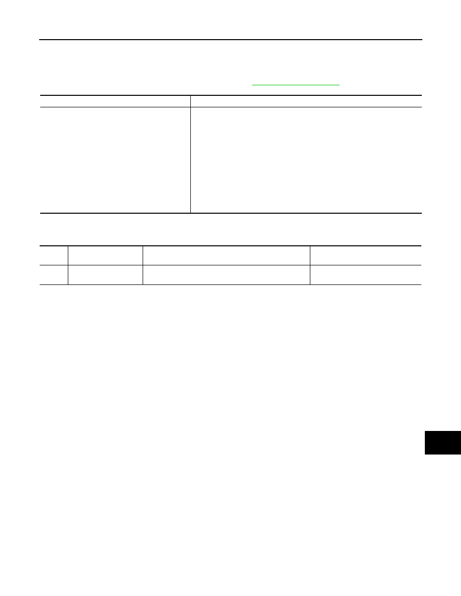
U1310
CONTROL UNIT (AV)
[U1310]
An initial diagnosis error is detected in AV communication
circuit.
Replace AV control unit.

AV-210
< COMPONENT DIAGNOSIS >
[BOSE AUDIO WITHOUT NAVIGATION]
U1200 AV CONTROL UNIT
U1200 AV CONTROL UNIT
Description
INFOID:0000000003544749
Replace the AV control unit if this DTC is displayed. Refer to
.
DTC Logic
INFOID:0000000003544750
Part name
Description
AV CONTROL UNIT
• It is the master unit of the MULTI AV system, and it is connected to each control
unit by communication. It operates each system according to communication
signals from the AV control unit.
• AV control unit includes audio function and vehicle information function.
• It is connected to ECM and unified meter and A/C amp via CAN communica-
tion to obtain necessary information for the vehicle information function.
• It is connected to BCM via CAN communication transmitting/receiving for the
vehicle settings function.
• It inputs the illumination signals that are required for the display dimming con-
trol.
• It inputs the signals for driving status recognition (vehicle speed, reverse and
parking brake).
• Auxiliary image signal is input from the auxiliary input jacks.
DTC
Display contents of
CONSULT-III
DTC Detection Condition
Action to take
U1200
Cont Unit
FLASH- ROM
[U1200]
An internal malfunction is detected in AV control unit
(FLASH-ROM).
Replace AV control unit.
AV
U1216 AV CONTROL UNIT
AV-211
< COMPONENT DIAGNOSIS >
[BOSE AUDIO WITHOUT NAVIGATION]
C
D
E
F
G
H
I
J
K
L
M
B
A
O
P
U1216 AV CONTROL UNIT
Description
INFOID:0000000003544751
Replace the AV control unit if this DTC is displayed. Refer to
DTC Logic
INFOID:0000000003544752
Part name
Description
AV CONTROL UNIT
• It is the master unit of the MULTI AV system, and it is connected to each control
unit by communication. It operates each system according to communication
signals from the AV control unit.
• AV control unit includes audio function and vehicle information function.
• It is connected to ECM and unified meter and A/C amp via CAN communica-
tion to obtain necessary information for the vehicle information function.
• It is connected to BCM via CAN communication transmitting/receiving for the
vehicle settings function.
• It inputs the illumination signals that are required for the display dimming con-
trol.
• It inputs the signals for driving status recognition (vehicle speed, reverse and
parking brake).
• Auxiliary image signal is input from the auxiliary input jacks.
DTC
Display contents of
CONSULT-III
DTC Detection Condition
Action to take
U1216
CAN CONT
[U1216]
Internal malfunction of AV control unit (CAN controller) is
detected.
Replace AV control unit.
AV-212
< COMPONENT DIAGNOSIS >
[BOSE AUDIO WITHOUT NAVIGATION]
U1243 DISPLAY UNIT
U1243 DISPLAY UNIT
Description
INFOID:0000000003544753
DTC Logic
INFOID:0000000003544754
Diagnosis Procedure
INFOID:0000000003544755
1.
CHECK DISPLAY UNIT POWER SUPPLY AND GROUND CIRCUIT
Check display unit power supply and ground circuits. Refer to
AV-218, "DISPLAY UNIT : Diagnosis Proce-
.
Is the inspection result normal?
YES
>> GO TO 2.
NO
>> Repair malfunctioning parts.
2.
CHECK CONTINUITY COMMUNICATION CIRCUIT
1.
Turn ignition switch OFF.
2.
Disconnect display unit connector and AV control unit connector.
3.
Check continuity between display unit harness connector and AV control unit harness connector.
4.
Check continuity between display unit harness connector and ground.
Is the inspection result normal?
YES
>> GO TO 3.
NO
>> Repair harness or connector.
3.
CHECK COMMUNICATION SIGNAL (CONT
→
DISP)
1.
Connect display unit connector and AV control unit connector.
2.
Turn ignition switch ON.
3.
Check signal between display unit harness connector and ground.
Part name
Description
DISPLAY UNIT
• Display image is controlled by the serial communication from AV control unit.
• Inputs the RGB image signal (RGB, RGB area and RGB synchronizing) from
AV control unit and the auxiliary image signal from the auxiliary input jacks.
• Outputs the synchronizing signals (HP and VP) to the AV control unit.
DTC
Display contents of
CONSULT-III
DTC Detection Condition
Possible causes
U1243
FRONT DISP CONN
[U1243]
When either one of the following items is detected:
• Display unit power supply and ground circuits malfunc-
tion is detected.
• Malfunction is detected in communication circuits be-
tween AV control unit and display unit.
• Display unit power supply and
ground circuits.
• Communication circuits between
AV control unit and display unit.
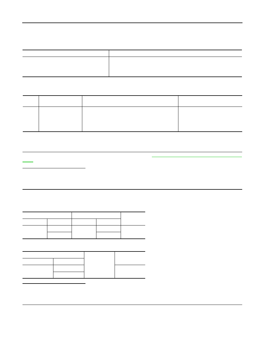
Display unit
AV control unit
Continuity
Connector
Terminals
Connector
Terminals
M71
11
M83
56
Existed
22
44
Display unit
Ground
Continuity
Connector
Terminals
M71
11
Not existed
22
Нет комментариевНе стесняйтесь поделиться с нами вашим ценным мнением.
Текст