Infiniti EX35. Manual — part 665
EC-402
< COMPONENT DIAGNOSIS >
[VQ35HR]
P1572 ASCD BRAKE SWITCH
Follow the procedure “With CONSULT-III” above.
Is 1st trip DTC detected?
YES
>> Go to
NO
>> GO TO 3.
3.
PERFORM DTC CONFIRMATION PROCEDURE
With CONSULT-III
1.
Drive the vehicle for at least 5 consecutive seconds under the following conditions.
CAUTION:
Always drive vehicle at a safe speed.
NOTE:
This procedure may be conducted with the drive wheels lifted in the shop or by driving the vehicle.
If a road test is expected to be easier, it is unnecessary to lift the vehicle.
2.
Check 1st trip DTC.
With GST
Follow the procedure “With CONSULT-III” above.
Is 1st trip DTC detected?
YES
>> Go to
NO
>> INSPECTION END
Diagnosis Procedure
INFOID:0000000003133575
1.
CHECK OVERALL FUNCTION-I
With CONSULT-III
1.
Turn ignition switch ON.
2.
Select “BRAKE SW1” in “DATA MONITOR” mode with CONSULT-III.
3.
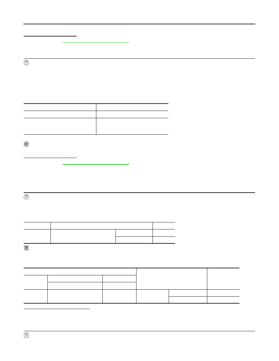
Check “BRAKE SW1” indication under the following conditions.
Without CONSULT-III
1.
Turn ignition switch ON.
2.
Check the voltage between ECM harness connector terminals as follows.
Is the inspection result normal?
YES
>> GO TO 2.
NO
>> GO TO 3.
2.
CHECK OVERALL FUNCTION-II
With CONSULT-III
Select “BRAKE SW2” and check indication under the following conditions.
VHCL SPEED SE
More than 30 km/h (19 mph)
Selector lever
Suitable position
Driving location
Depress the brake pedal for more than
five seconds so as not to come off from
the above-mentioned vehicle speed.
Monitor item
Condition
Indication
BRAKE SW1
Brake pedal
Slightly depressed
OFF
Fully released
ON
ECM
Condition
Voltage (V)
Connector
+
–
Terminal
Terminal
M107
126
(ASCD brake switch signal)
128
Brake pedal
Slightly depressed
Approx. 0
Fully released
Battery voltage
P1572 ASCD BRAKE SWITCH
EC-403
< COMPONENT DIAGNOSIS >
[VQ35HR]
C
D
E
F
G
H
I
J
K
L
M
A
EC
N
P
O
Without CONSULT-III
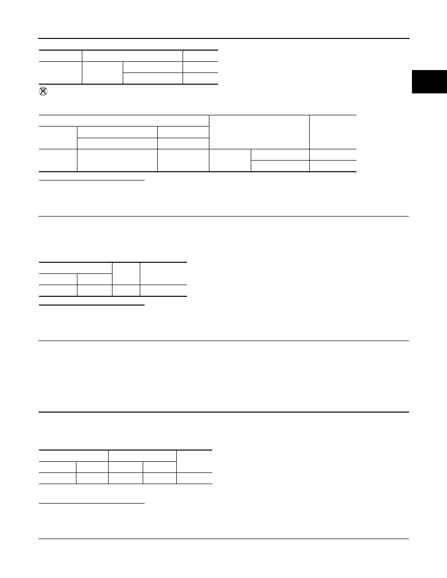
Check the voltage between ECM harness connector terminals under the following conditions.
Is the inspection result normal?
YES
>> GO TO 13.
NO
>> GO TO 8.
3.
CHECK ASCD BRAKE SWITCH POWER SUPPLY CIRCUIT
1.
Turn ignition switch OFF.
2.
Disconnect ASCD brake switch harness connector.
3.
Turn ignition switch ON.
4.
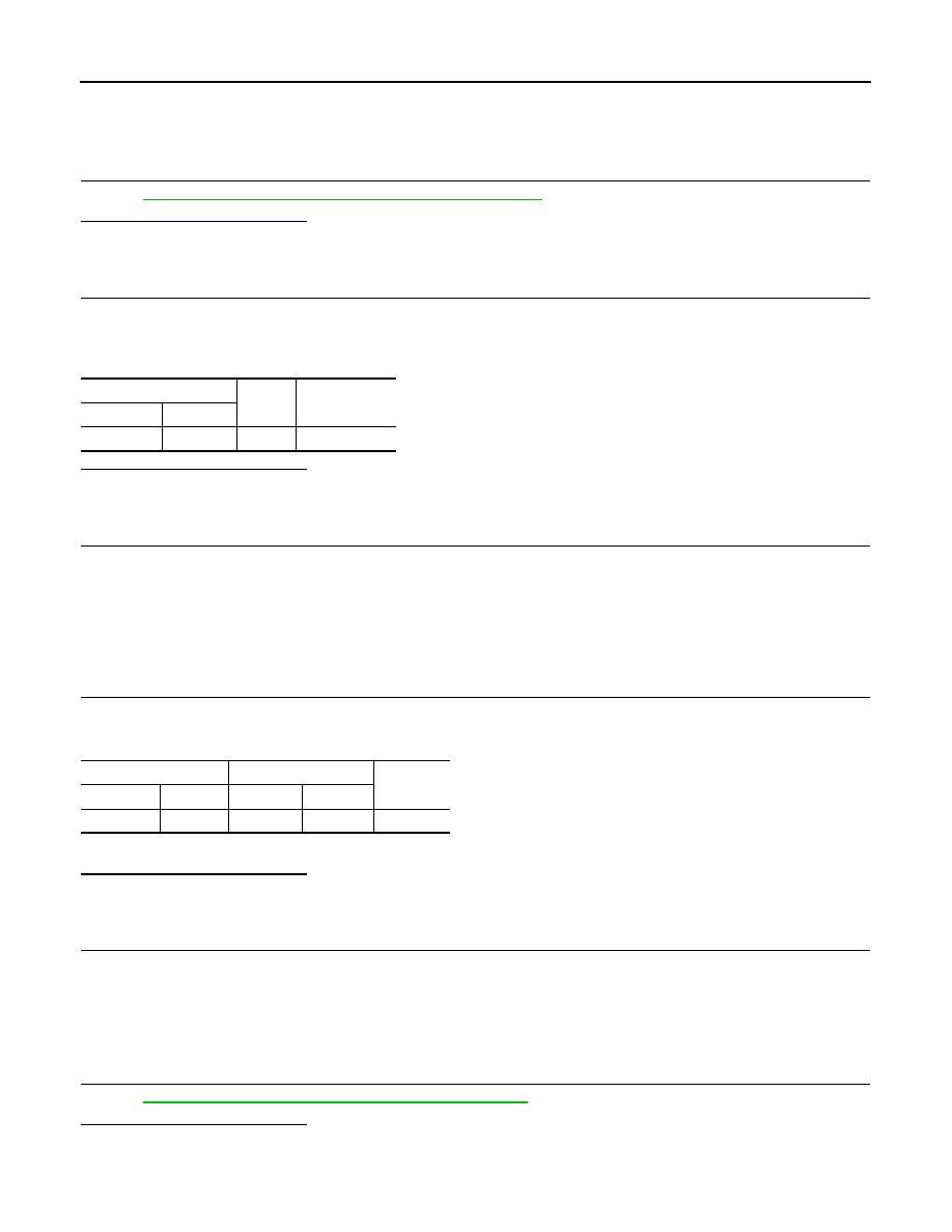
Check the voltage between ASCD brake switch harness connector and ground.
Is the inspection result normal?
YES
>> GO TO 5.
NO
>> GO TO 4.
4.
DETECT MALFUNCTIONING PART
Check the following.
• Fuse block (J/B) connector E103
• 10A fuse (No. 3)
• Harness for open or short between ASCD brake switch and fuse
>> Repair open circuit or short to ground in harness or connectors.
5.
CHECK ASCD BRAKE SWITCH INPUT SIGNAL CIRCUIT FOR OPEN AND SHORT
1.
Turn ignition switch OFF.
2.
Disconnect ECM harness connector.
3.
Check the continuity between ASCD brake switch harness connector and ECM harness connector.
4.
Also check harness for short to ground and short to power.
Is the inspection result normal?
YES
>> GO TO 7.
NO
>> GO TO 6.
6.
DETECT MALFUNCTIONING PART
Check the following.
• Harness connectors E106, M6
Monitor item
Condition
Indication
BRAKE SW2
Brake pedal
Slightly depressed
ON
Fully released
OFF
ECM
Condition
Voltage (V)
Connector
+
–
Terminal
Terminal
M107
122
(Stop lamp switch signal)
128
Brake pedal
Slightly depressed
Battery voltage
Fully released
Approx. 0
ASCD brake switch
Ground
Voltage
Connector
Terminal
E109
1
Ground
Battery voltage
ASCD brake switch
ECM
Continuity
Connector
Terminal
Connector
Terminal
E109
2
M107
126
Existed
EC-404
< COMPONENT DIAGNOSIS >
[VQ35HR]
P1572 ASCD BRAKE SWITCH
• Harness for open or short between ECM and ASCD brake switch
>> Repair open circuit or short to ground or short to power in harness or connectors.
7.
CHECK ASCD BRAKE SWITCH
EC-405, "Component Inspection (ASCD Brake Switch)"
Is the inspection result normal?
YES
>> GO TO 8.
NO
>> Replace ASCD brake switch.
8.
CHECK STOP LAMP SWITCH POWER SUPPLY CIRCUIT
1.
Turn ignition switch OFF.
2.
Disconnect stop lamp switch harness connector.
3.
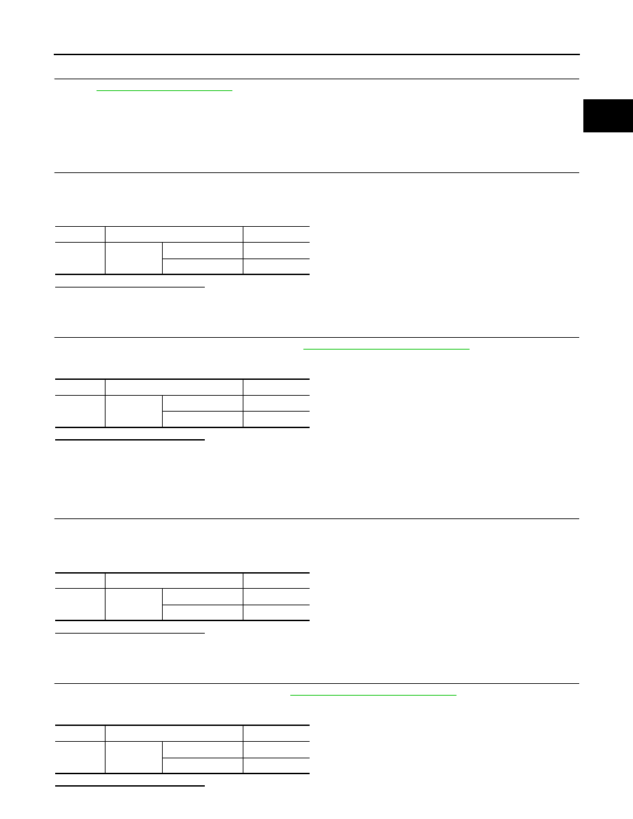
Check the voltage between stop lamp switch harness connector and ground.
Is the inspection result normal?
YES
>> GO TO 10.
NO
>> GO TO 9.
9.
DETECT MALFUNCTIONING PART
Check the following.
• Fuse block (J/B) connector E103
• 10A fuse (No. 7)
• Harness for open or short between stop lamp switch and battery
>> Repair open circuit or short to ground or short to power in harness or connectors.
10.
CHECK STOP LAMP SWITCH INPUT SIGNAL CIRCUIT FOR OPEN AND SHORT
1.
Disconnect ECM harness connector.
2.
Check the continuity between stop lamp switch harness connector and ECM harness connector.
3.
Also check harness for short to ground and short to power.
Is the inspection result normal?
YES
>> GO TO 12.
NO
>> GO TO 11.
11.
DETECT MALFUNCTIONING PART
Check the following.
• Fuse block (J/B) connectors E103, M2
• Harness for open or short between ECM and stop lamp switch
>> Repair open circuit or short to ground or short to power in harness or connectors.
12.
CHECK STOP LAMP SWITCH
EC-405, "Component Inspection (Stop Lamp Switch)"
.
Is the inspection result normal?
YES
>> GO TO 13.
NO
>> Replace stop lamp switch.
Stop lamp switch
Ground
Voltage
Connector
Terminal
E110
3
Ground
Battery voltage
Stop lamp switch
ECM
Continuity
Connector
Terminal
Connector
Terminal
E110
4
M107
122
Existed
P1572 ASCD BRAKE SWITCH
EC-405
< COMPONENT DIAGNOSIS >
[VQ35HR]
C
D
E
F
G
H
I
J
K
L
M
A
EC
N
P
O
13.
CHECK INTERMITTENT INCIDENT
GI-38, "Intermittent Incident"
.
>> INSPECTION END
Component Inspection (ASCD Brake Switch)
INFOID:0000000003133576
1.
CHECK ASCD BRAKE SWITCH-I
1.
Turn ignition switch OFF.
2.
Disconnect ASCD brake switch harness connector.
3.
Check the continuity between ASCD brake switch terminals under the following conditions.
Is the inspection result normal?
YES
>> INSPECTION END
NO
>> GO TO 2.
2.
CHECK ASCD BRAKE SWITCH-II
1.
Adjust ASCD brake switch installation. Refer to
BR-7, "Inspection and Adjustment"
.
2.
Check the continuity between ASCD brake switch terminals under the following conditions.
Is the inspection result normal?
YES
>> INSPECTION END
NO
>> Replace ASCD brake switch.
Component Inspection (Stop Lamp Switch)
INFOID:0000000003133578
1.
CHECK STOP LAMP SWITCH-I
1.
Turn ignition switch OFF.
2.
Disconnect stop lamp switch harness connector.
3.
Check the continuity between stop lamp switch terminals under the following conditions.
Is the inspection result normal?
YES
>> INSPECTION END
NO
>> GO TO 2.
2.
CHECK STOP LAMP SWITCH-II
1.
Adjust stop lamp switch installation. Refer to
BR-7, "Inspection and Adjustment"
2.
Check the continuity between stop lamp switch terminals under the following conditions.
Is the inspection result normal?
Terminals
Condition
Continuity
1 and 2
Brake pedal
Fully released
Existed
Slightly depressed
Not existed
Terminals
Condition
Continuity
1 and 2
Brake pedal
Fully released
Existed
Slightly depressed
Not existed
Terminals
Condition
Continuity
3 and 4
Brake pedal
Fully released
Not existed
Slightly depressed
Existed
Terminals
Condition
Continuity
3 and 4
Brake pedal
Fully released
Not existed
Slightly depressed
Existed
Нет комментариевНе стесняйтесь поделиться с нами вашим ценным мнением.
Текст