Infiniti EX35. Manual — part 664
EC-398
< COMPONENT DIAGNOSIS >
[VQ35HR]
P1564 ICC STEERING SWITCH
Check the following.
• Combination switch (spiral cable)
• Harness for open and short between ECM and combination switch
>> Repair open circuit or short to ground or short to power in harness or connectors.
5.
CHECK ICC STEERING SWITCH INPUT SIGNAL CIRCUIT FOR OPEN AND SHORT
1.
Check the continuity between combination switch and ECM harness connector.
2.
Also check harness for short to ground and short to power.
Is the inspection result normal?
YES
>> GO TO 7.
NO
>> GO TO 6.
6.
DETECT MALFUNCTIONING PART
Check the following.
• Combination switch (spiral cable)
• Harness for open and short between ECM and combination switch
>> Repair open circuit or short to ground or short to power in harness or connectors.
7.
CHECK ICC STEERING SWITCH
EC-398, "Component Inspection"
Is the inspection result normal?
YES
>> GO TO 8.
NO
>> Replace ICC steering switch.
8.
CHECK INTERMITTENT INCIDENT
GI-38, "Intermittent Incident"
>> INSPECTION END
Component Inspection
INFOID:0000000003133570
1.
CHECK ICC STEERING SWITCH
1.
Turn ignition switch OFF.
2.
Disconnect combination switch (spiral cable) harness connector M303.
3.
Check resistance between combination switch harness connector terminals under the following condi-
tions.
Is the inspection result normal?
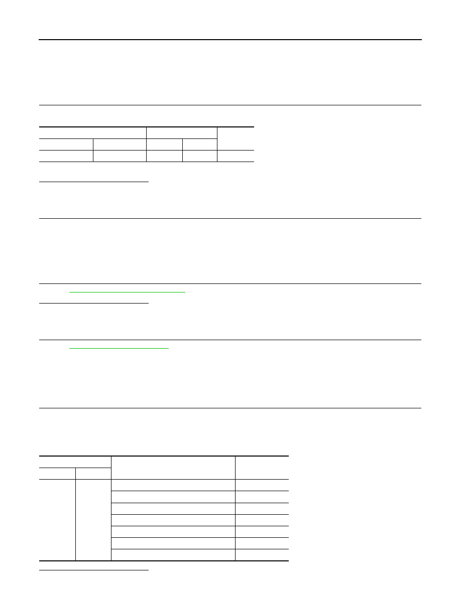
Combination switch
ECM
Continuity
Connector
Terminal
Connector
Terminal
M303
13
M107
101
Existed
Combination switch
Condition
Resistance (
Ω
)
Connector
Terminals
M303
13 and 16
MAIN switch: Pressed
Approx. 0
LDP switch: Pressed
Approx. 270
CANCEL switch: Pressed
Approx. 620
DISTANCE switch: Pressed
Approx. 1,100
SET/COAST switch: Pressed
Approx. 1,810
RESUME/ACCELERATE switch: Pressed
Approx. 3,000
All ICC steering switches: Released
Approx. 5,420
P1564 ICC STEERING SWITCH
EC-399
< COMPONENT DIAGNOSIS >
[VQ35HR]
C
D
E
F
G
H
I
J
K
L
M
A
EC
N
P
O
YES
>> INSPECTION END
NO
>> Replace ICC steering switch

EC-400
< COMPONENT DIAGNOSIS >
[VQ35HR]
P1568 ICC FUNCTION
P1568 ICC FUNCTION
DTC Logic
INFOID:0000000003133571
DTC DETECTION LOGIC
NOTE:
• If DTC P1568 is displayed with DTC U1000 or U1001, first perform the trouble diagnosis for DTC
U1000, U1001. Refer to
.
• If DTC P1568 is displayed with DTC P0607, first perform the trouble diagnosis for DTC P0607. Refer
• If DTC P1568 is displayed with DTC P0605, first perform the trouble diagnosis for DTC P0605. Refer
DTC CONFIRMATION PROCEDURE
1.
PRECONDITIONING
If DTC Confirmation Procedure has been previously conducted, always turn ignition switch OFF and wait at
least 10 seconds before conducting the next test.
TESTING CONDITION:
Step 2 may be conducted with the drive wheels lifted in the shop or by driving the vehicle. If a road test
is expected to be easier, it is unnecessary to lift the vehicle.
>> GO TO 2.
2.
PERFORM DTC CONFIRMATION PROCEDURE
1.
Turn ignition switch ON.
2.
Press MAIN switch on ICC steering switch.
3.
Drive the vehicle at more than 40 km/h (25 MPH).
CAUTION:
Always drive vehicle at a safe speed.
4.
Press SET/COAST switch.
5.
Check DTC.
Is DTC detected?
YES
>> Go to
NO
>> INSPECTION END
Diagnosis Procedure
INFOID:0000000003133572
1.
REPLACE ICC SENSOR INTEGRATED UNIT
1.
Replace ICC sensor integrated unit.
2.
Perform
CCS-13, "ACTION TEST : Special Repair Requirement (Vehicle-To-Vehicle Distance Control
.
3.
Check DTC of ICC sensor integrated unit. Refer to
CCS-23, "Diagnosis Description"
>> INSPECTION END
DTC No.
Trouble Diagnosis
Name
DTC Detecting Condition
Possible Cause
P1568
ICC function
ECM detects a difference between signals
from ICC sensor integrated unit is out of spec-
ified range.
• Harness or connectors
(The CAN communication line is open or
shorted.)
• ICC sensor integrated unit
• ECM

P1572 ASCD BRAKE SWITCH
EC-401
< COMPONENT DIAGNOSIS >
[VQ35HR]
C
D
E
F
G
H
I
J
K
L
M
A
EC
N
P
O
P1572 ASCD BRAKE SWITCH
Description
INFOID:0000000003133573
When the brake pedal is depressed, ASCD brake switch is turned OFF and stop lamp switch is turned ON.
ECM detects the state of the brake pedal by this input of two kinds (ON/OFF signal).
Refer to
for the ASCD function.
DTC Logic
INFOID:0000000003133574
DTC DETECTION LOGIC
NOTE:
• If DTC P1572 is displayed with DTC P0605, first perform the trouble diagnosis for DTC P0605. Refer
.
• This self-diagnosis has the one trip detection logic. When malfunction A is detected, DTC is not
stored in ECM memory. And in that case, 1st trip DTC and 1st trip freeze frame data are displayed.
1st trip DTC is erased when ignition switch OFF. And even when malfunction A is detected in two
consecutive trips, DTC is not stored in ECM memory.
DTC CONFIRMATION PROCEDURE
1.
PRECONDITIONING
If DTC Confirmation Procedure has been previously conducted, always turn ignition switch OFF and wait at
least 10 seconds before conducting the next test.
NOTE:
Procedure for malfunction B is not described here. It takes extremely long time to complete procedure for mal-
function B. By performing procedure for malfunction A, the incident that causes malfunction B can be
detected.
>> GO TO 2.
2.
PERFORM DTC CONFIRMATION PROCEDURE FOR MALFUNCTION A
With CONSULT-III
1.
Start engine (VDC switch OFF).
2.
Select “DATA MONITOR” mode with CONSULT-III.
3.
Press MAIN switch and make sure that CRUISE lamp lights up.
4.
Drive the vehicle for at least 5 consecutive seconds under the following conditions.
CAUTION:
Always drive vehicle at a safe speed.
NOTE:
This procedure may be conducted with the drive wheels lifted in the shop or by driving the vehicle.
If a road test is expected to be easier, it is unnecessary to lift the vehicle.
5.
Check 1st trip DTC.
With GST
DTC No.
Trouble diagnosis
name
DTC detecting condition
Possible cause
P1572
ASCD brake switch
A)
When the vehicle speed is above 30 km/h
(19 MPH), ON signals from the stop lamp
switch and the ASCD brake switch are sent
to the ECM at the same time.
• Harness or connectors
(The stop lamp switch circuit is shorted.)
• Harness or connectors
(The ASCD brake switch circuit is shorted.)
• Stop lamp switch
• ASCD brake switch
• Incorrect stop lamp switch installation
• Incorrect ASCD brake switch installation
• ECM
B)
ASCD brake switch signal is not sent to
ECM for extremely long time while the ve-
hicle is driving.
VHCL SPEED SE
More than 30 km/h (19 mph)
Selector lever
Suitable position
Нет комментариевНе стесняйтесь поделиться с нами вашим ценным мнением.
Текст