Infiniti EX35. Manual — part 709
EXHAUST MANIFOLD
EM-35
< ON-VEHICLE REPAIR >
C
D
E
F
G
H
I
J
K
L
M
A
EM
N
P
O
8.
Disconnect air fuel ratio sensor 1 harness connectors (bank 1 and bank 2) and remove harness clip.
9.
Using the heated oxygen sensor wrench [SST: KV10114400
(J38365)] (C), remove air fuel ratio sensor 1 (bank 1 and bank
2).
CAUTION:
• Be careful not to damage air fuel ratio sensor 1.
• Discard any air fuel ratio sensor 1 which has been
dropped onto a hard surface such as a concrete floor.
Replace with a new sensor.
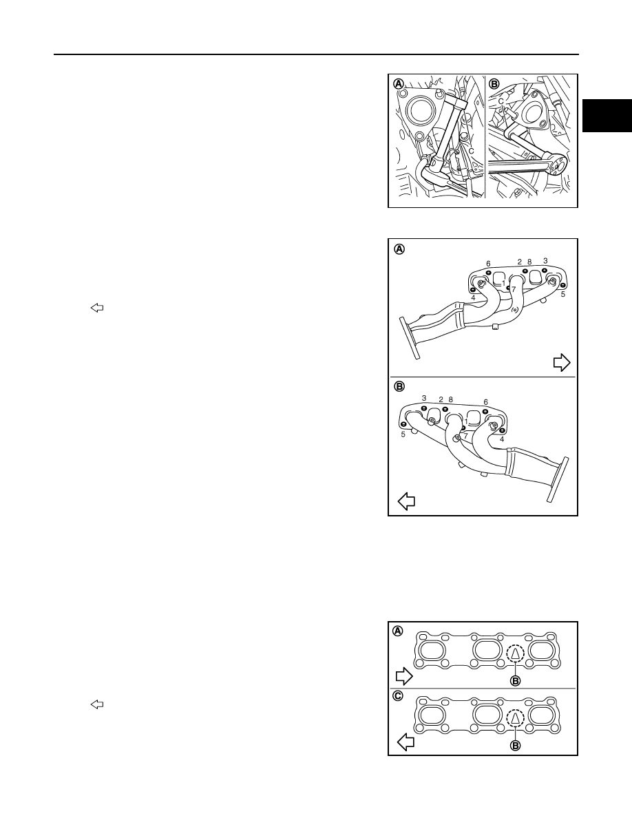
10. Remove exhaust manifold cover (upper) (bank 1 and bank 2).
11. Loosen mounting nuts in the reverse order as shown in the fig-
ure to remove exhaust manifold.
NOTE:
Disregard the numerical order No. 7 and 8 in removal.
12. Remove gaskets.
CAUTION:
Cover engine openings to avoid entry of foreign materials.
INSTALLATION
Note the following, and install in the reverse order of removal.
EXHAUST MANIFOLD GASKET
• Install exhaust manifold gasket in direction shown in the figure.
(Follow same procedure for both banks.)
EXHAUST MANIFOLD
A
: Bank 2
B
: Bank 1
JPBIA0271ZZ
A
: Bank 1
B
: Bank 2
: Engine front
JPBIA0017ZZ
A
: Bank 1
B
: Triangle press
C
: Bank 2
: Engine front
JPBIA0019ZZ
EM-36
< ON-VEHICLE REPAIR >
EXHAUST MANIFOLD
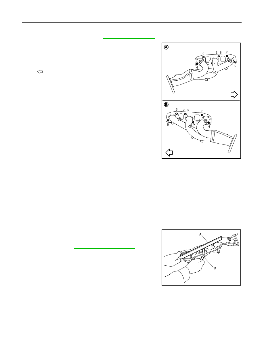
• If stud bolts were removed, install them and tighten to the specified torque below.
• Install exhaust manifold and tighten mounting nuts in numerical
order as shown in the figure.
NOTE:
Tighten nuts No. 1 and 2 in two steps. The numerical order No. 7
and 8 shows second step.
AIR FUEL RATIO SENSOR 1
CAUTION:
• Before installing a new air fuel ratio sensor 1, clean exhaust system threads using heated oxygen
sensor thread cleaner tool (commercial service tool: J-43897-18 or J-43897-12) and apply anti-seize
lubricant.
• Never over torque air fuel ratio sensor 1. Doing so may cause damage to air fuel ratio sensor 1,
resulting in the “MIL” coming on.
Inspection
INFOID:0000000003139106
INSPECTION AFTER REMOVAL
Surface Distortion
• Check the surface distortion of the exhaust manifold mating sur-
face with a straightedge (A) and a feeler gauge (B).
• If it exceeds the limit, replace exhaust manifold.
Tightening torque
A
: Bank 1
B
: Bank 2
: Engine front
JPBIA0017ZZ
Limit
: Refer to
.
JPBIA0018ZZ
FUEL INJECTOR AND FUEL TUBE
EM-37
< ON-VEHICLE REPAIR >
C
D
E
F
G
H
I
J
K
L
M
A
EM
N
P
O
FUEL INJECTOR AND FUEL TUBE
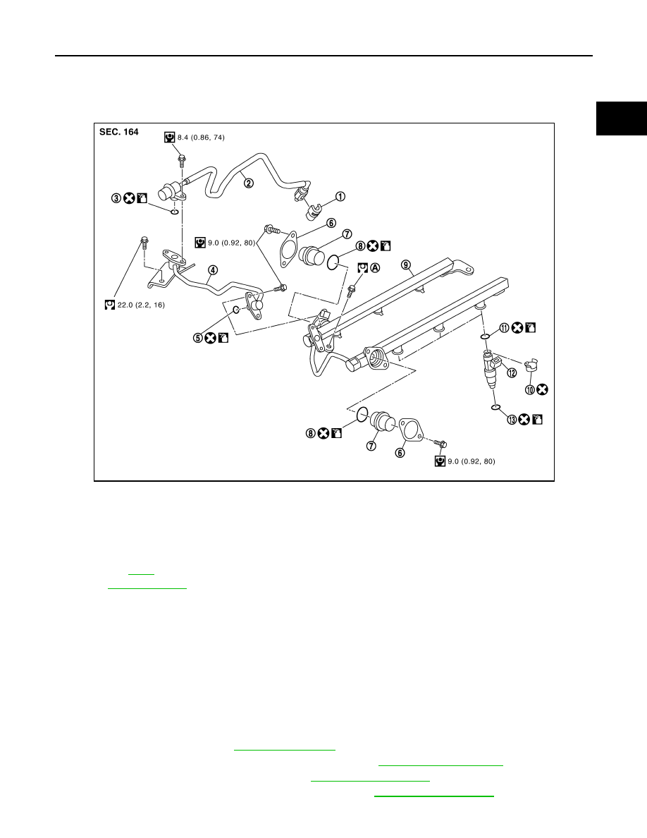
Exploded View
INFOID:0000000003139107
CAUTION:
Never remove or disassemble parts unless instructed as shown in the figure.
Removal and Installation
INFOID:0000000003139108
REMOVAL
WARNING:
• Put a “CAUTION: FLAMMABLE” sign in the workshop.
• Be sure to work in a well ventilated area and furnish workshop with a CO
2
fire extinguisher.
• Never smoke while servicing fuel system. Keep open flames and sparks away from the work area.
• Never drain engine coolant when the engine is hot to avoid the danger of being scalded.
1.
Release fuel pressure. Refer to
.
2.
Disconnect battery cable from the negative terminal. Refer to
.
3.
Remove engine cover with power tool. Refer to
.
4.
Remove air cleaner case and air duct (RH and LH). Refer to
.
1.
Quick connector cap
2.
Fuel feed hose (with damper)
3.
O-ring
4.
Fuel sub tube
5.
O-ring
6.
Fuel damper cap
7.
Fuel damper
8.
O-ring
9.
Fuel tube
10. Clip
11. O-ring (black)
12. Fuel injector
13. O-ring (green)
A.
Refer to
Refer to
for symbols in the figure.
JPBIA1708GB
EM-38
< ON-VEHICLE REPAIR >
FUEL INJECTOR AND FUEL TUBE
5.
Remove intake manifold collector. Refer to
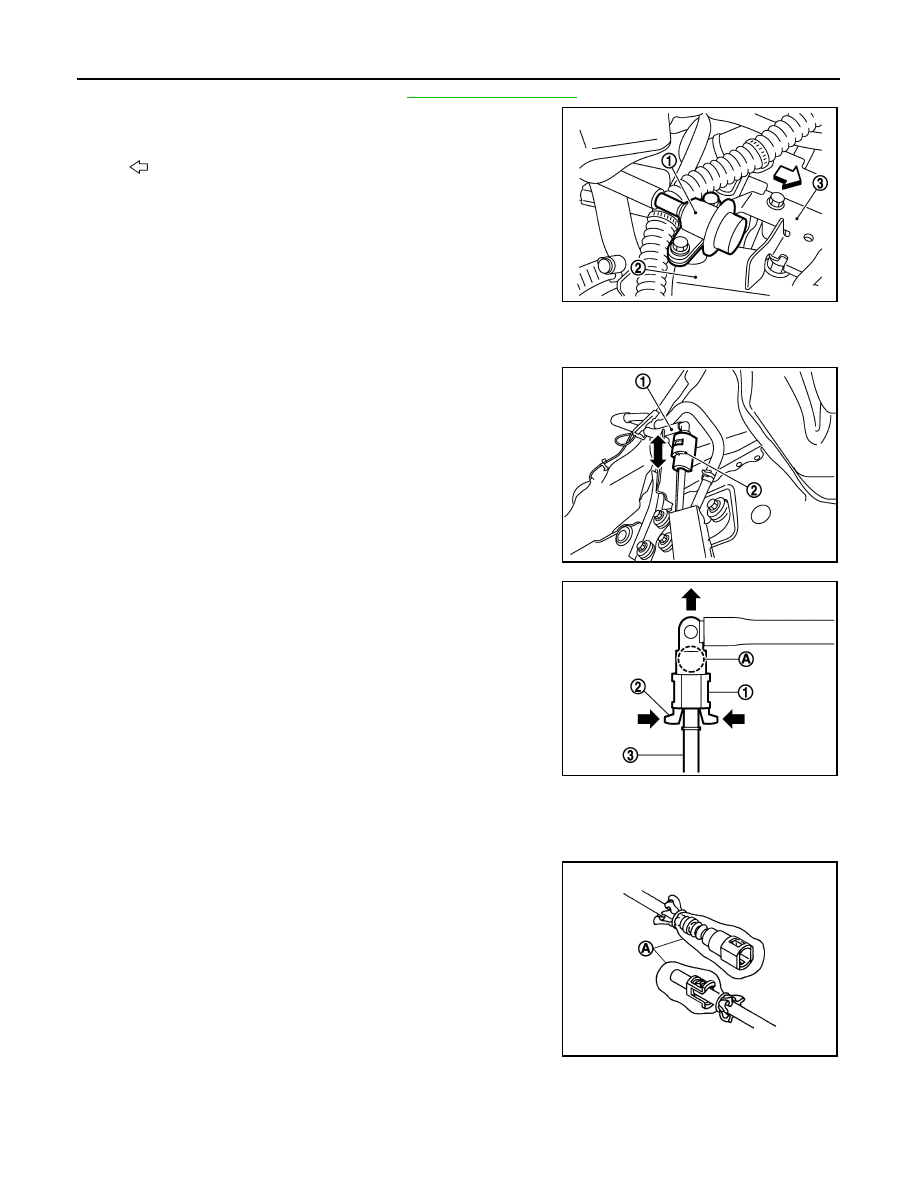
6.
Remove fuel feed hose (with damper) (1) from fuel sub-tube (2)
and remove harness bracket (3).
NOTE:
There is no fuel return route.
CAUTION:
• While hoses are disconnected, plug them to prevent fuel
from draining.
• Never separate damper and hose.
7.
When separating fuel feed hose (with damper) and centralized under-floor piping connection, disconnect
quick connector as follows:
a.
Remove quick connector cap (2) from quick connector connec-
tion on right member side.
b.
Disconnect fuel feed hose (with damper) (1) from bracket hose
clamp.
c.
Push in retainer tabs (2).
d.
Draw and pull out quick connector (1) straight from centralized
under-floor piping (3).
CAUTION:
• Pull quick connector holding position (A) as shown in the
figure.
• Never pull with lateral force applied. O-ring inside quick
connector may be damaged.
• Prepare container and cloth beforehand as fuel will leak
out.
• Avoid fire and sparks.
• Keep parts away from heat source. Especially, be careful
when welding is performed around them.
• Never expose parts to battery electrolyte or other acids.
• Never bend or twist connection between quick connector and fuel feed hose (with damper) dur-
ing installation/removal.
• To keep clean the connecting portion and to avoid dam-
age and foreign materials, cover them completely with
plastic bags, etc. (A) or something similar.
8.
Remove fuel sub tube mounting bolt.
9.
Disconnect harness connector from fuel injector.
: Engine front
JPBIA0032ZZ
JPBIA0254ZZ
JPBIA1854ZZ
JPBIA0135ZZ
Нет комментариевНе стесняйтесь поделиться с нами вашим ценным мнением.
Текст