SsangYong Korando II (1996-2006 year). Manual — part 209
SSANGYONG MY2002
2C-6 FRONT SUSPENSION
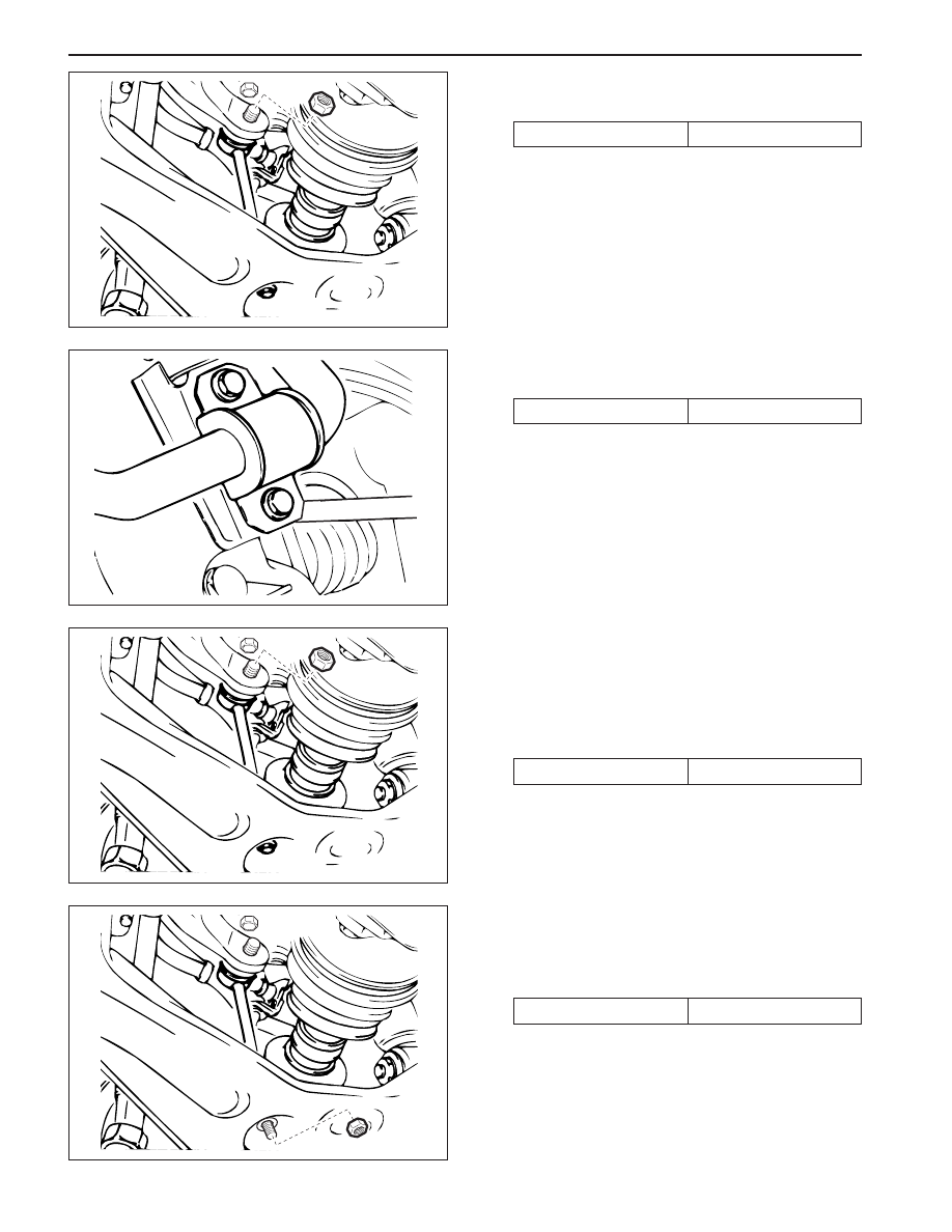
3. Remove the front stabilizer-to-stabilizer link nuts.
Installation Notice
KAA2C080
KAA2C090
KAA2C080
KAA2C100
4. Remove the front stabilizer mounting bolts.
Installation Notice
Tightening Torque
70 N•m (52 lb-ft)
5. Installation should follow the removal procedure
in the reverse order.
STABILIZER LINK
Removal and Installation Procedure
1. Raise and suitably support the vehicle.
2. Remove the front stabilizer-to-stabilizer link nuts.
Installation Notice
3. Remove the stabilizer link-to-lower control arm
nuts.
4. Remove the stabilizer link.
Installation Notice
Tightening Torque
19 N•m (14 lb-ft)
Tightening Torque
38 N•m (28 lb-ft)
Tightening Torque
70 N•m (52 lb-ft)
•
The distance between the end of the nut and
the end of the stabilizer link should be 10 - 12
mm (0.39 - 0.47 inch) at the connection of the
stabilizer link and lower control arm.
5. Installation should follow the removal procedure
in the reverse order.

FRONT SUSPENSION 2C-7
SSANGYONG MY2002
TORSION BAR
Removal and Installation Procedure
1. Raise and suitably support the vehicle.
2. Remove the height control bolt.
Notice:
•
Install the torsion bar and adjust the distance
be tween the end of the height control blot and
piece end of the bolt to be 50 - 55 mm (1.97 -
2.17 inch). Adjust the vehicle height.
KAA2C110
KAA2C120
KAA2C130
3. Remove the torsion bar fixing nuts and bolts and
then withdraw the torsion bar.
Installation Notice
•
Check and adjust the wheel alignment.
4. Installation should follow the removal procedure
in the reverse order.
LOWER CONTROL ARM
Tools Required
661 589 13 33 00 Ball Joint Remover
Removal and Installation Procedure
1. Raise and suitably support the vehicle.
2. Remove the front wheels. Refer to Section 2E,
Tires and Wheels.
3. Remove the torsion bar. Refer to “Torsion Bar” in
this section.
4. Remove the front shock absorber lower mounting
bolt and nut.
Installation Notice
Tightening Torque
70 N•m (52 lb-ft)
Tightening
Torque
M10
M12
50 N•m (37 lb-ft)
70 N•m (52 lb-ft)

SSANGYONG MY2002
2C-8 FRONT SUSPENSION
5. Remove the stabilizer link-to-lower control arm nut.
Installation Notice
KAA2C100
KAA2C140
KAA2C150
KAA2C160
6. Remove the lower ball joint using the ball joint
remover 661 589 13 33 00.
Installation Notice
Tightening Torque
19 N•m (14 lb-ft)
7. Remove the lower control arm mounting bolts.
Installation Notice
UPPER CONTROL ARM
Tools Required
661589 13 33 00 BallJointRemover
Removal and Installation Procedure
1. Raise and suitably support the vehicle.
2. Remove the front wheels. Refer to Section 2E,
Tires and Wheels.
3. Remove the front shock absorber upper mounting nut.
Notice:
•
The distance between the nut end and the screw
end is 6 - 9 mm (0.24 - 0.35 inch).
Tightening Torque
150 N•m (111 lb-ft)
Tightening Torque
120 N•m (89 lb-ft)
•
The distance between the end of the nut and
the end of the stabilizer link should be 10 - 12
mm (0.39 - 0.47 inch) at the connection of the
stabilizer link and lower control arm.
8. Installation should follow the removal procedure
in the reverse order.

FRONT SUSPENSION 2C-9
SSANGYONG MY2002
4. Remove the upper ball joint using the ball joint
remover 661 589 13 33 00.
Installation Notice
KAA2C170
KAA2C180
KAA2C130
KAA2C160
5. Remove the fulcrum pin mounting bolts and nuts
and remove the upper control arm.
Removal Notice
Tightening Torque
115 N•m (85 lb-ft)
FRONT SHOCK ABSORBER
Removal and Installation Procedure
1. Raise and suitably support the vehicle.
2. Remove the front wheels. Refer to Section 2E,
Tires and Wheels.
3. Remove the front shock absorber lower mounting
bolt and nut.
Removal Notice
4. Remove the front shock absorber upper mounting
nut.
Notice:
•
The distance between the nut end and the screw
end is 6 - 9 mm (0.24 - 0.35 inch).
5. Installation should follow the removal procedure
in the reverse order.
Tightening Torque
130 N•m (96 lb-ft)
Tightening Torque
70 N•m (52 lb-ft)
•
Be careful not to damage or lose the adjusting
shims.
•
Check and adjust the wheel alignment.
6. Installation should follow the removal procedure
in the reverse order.
Нет комментариевНе стесняйтесь поделиться с нами вашим ценным мнением.
Текст