SsangYong Korando II (1996-2006 year). Manual — part 27

1B1 -- 80 M162 ENGINE MECHANICAL
DAEWOO MY_2000
PISTON
Preceding Work: Removal of engine
Removal of cylinder head
Removal of oil pan
Removal of oil pump
Removal of baffle plate
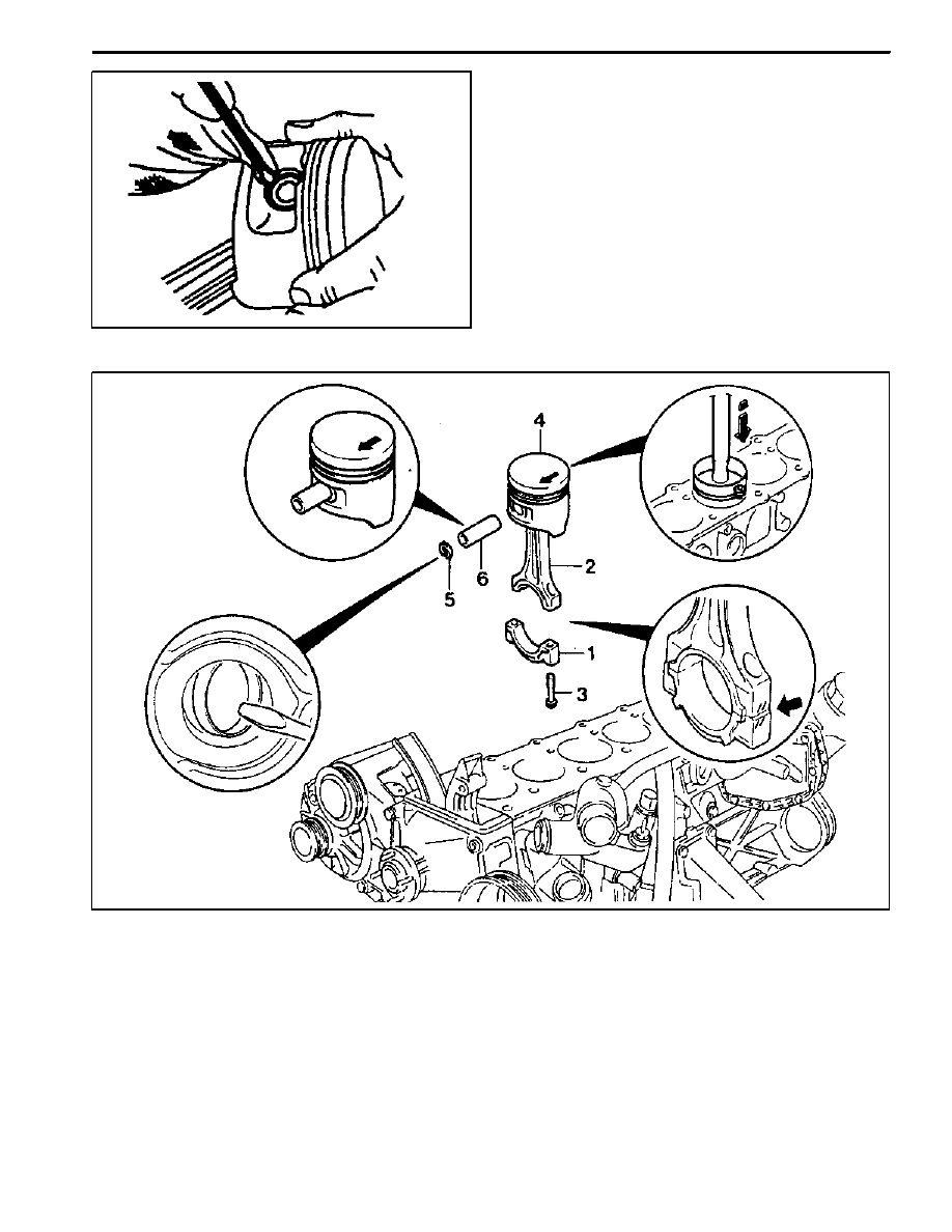
1 Connecting Rod Bearing Cap
2 Connecting Rod
3 Connecting Rod Bearing Cap Bolt
(M9 x 52, 12 pieces)
1st step 40 NSm (30 lb-ft)
. . . . . . . . . . . . . . . . . .
2nd step 90°
4 Piston
5 Snap Ring
6 Piston Pin
M162 ENGINE MECHANICAL 1B1 -- 81
DAEWOO MY_2000
Removal Procedure
1. Unscrew the connecting rod bearing cap bolt (3) and
remove the cap.
2. Remove the connecting rod and the piston upward.
Notice: Make sure that the bearing cap and shell are not
changed each other.
3. Remove the snap ring (5) and pull out the piston pin
(6).
Notice: Remove the snap ring using a clean cloth as
shown in the right picture so that the piston, piston ring,
and the snap ring don’t get damaged.

1B1 -- 82 M162 ENGINE MECHANICAL
DAEWOO MY_2000
Installation Procedure
1. Check the piston ring gap and apply the engine oil to
the piston pin and the connecting rod bushing.
2. Connect the piston and the connecting rod by press-
ing in the piston pin (6) and install the snap ring to the
groove.
3. Clean the cylinder bore, connecting rod bearing jour-
nal, connecting rod bearing shell and the piston and
coat them with engine oil.
4. Install the piston ring.
5. Install the piston so that the arrow on the piston head
faces to the forward of the vehicle.
6. After aligning the connecting rod and the bearing cap
mark (// or a number), tighten the bolts.
Installation Notice
Tightening Torque
1st step: 40 NSm (30 lb-ft)
Tightening Torque
2nd step: 90°
Apply the engine oil to the bearing cap upper and low-
er bearing shells.
7. Check if the crankshaft rotates without any trouble by
rotating it.
M162 ENGINE MECHANICAL 1B1 -- 83
DAEWOO MY_2000
CONNECTING ROD
Preceding Work: Removal of piston
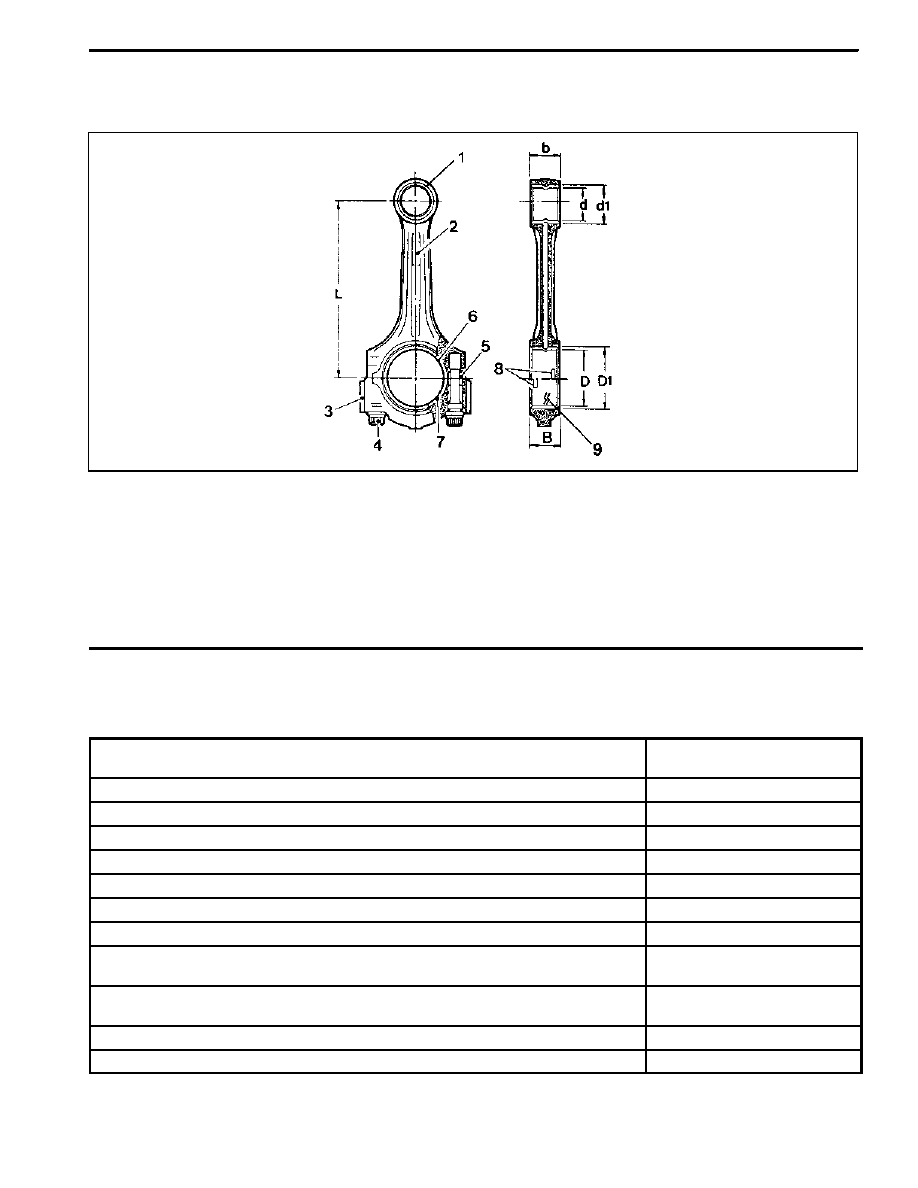
1 Connecting Rod Bushing
2 Oil Gallery
3 Balance Weight
4 Connecting Rod Bearing Cap Bolt
(M9 x 52, 12 m pieces)
1st step 40 NSm (30 lb-ft)
. . . . . . . . . . . . . . . . . .
2nd step 90°
5 Fit Sleeve
6 Upper Connecting Rod Bearing
7 Lower Connecting Rod Bearing
8 Bearing Shell Lug
9 Marking [Indication(//) or Numbers]
Service Data Standard
Distance (L) from The Connecting Rod Bearing Bore Center to The Bushing
Bore Center
145 ± 0.05 mm
Width of The Connecting Rod (B) at Bearing Bore
21.940 -- 22.000 mm
Width of The Connecting Rod (b) at Bushing Bore
21.940 -- 22.000 mm
Basic Bore at The Bearing Shell (D1)
51.600 -- 51.614 mm
Basic Bore at The Bushing (d1)
24.500 -- 24.521 mm
Bushing Inner Diameter (d)
22.007 -- 22.013 mm
Clearance Between The Piston Pin and The Bushing
0.007 -- 0.018 mm
Peak--to--valley Height of Connecting Rod Bushing on Inside
0.005 mm
Permissible Wwist of Connecting Rod Bearing Bore to Connecting Rod Bushing
Bore
0.15 mm
Permissible Deviation of Axial Paralleism of Connecting Rod Bearing Bore to
Connecting Rod Bushing Core
0.07 mm
Permissible Deviation of Connecting Rod Bearing Bore from Concentricity
0.01 mm
Permissible Difference of Each Connecting Rod in Weight
0.4 g
Нет комментариевНе стесняйтесь поделиться с нами вашим ценным мнением.
Текст