SsangYong Korando II (1996-2006 year). Manual — part 17
1B1 -- 34 M162 ENGINE MECHANICAL
DAEWOO MY_2000
Tools Required
601 589 03 43 00 Crankshaft Rear Seal Installer
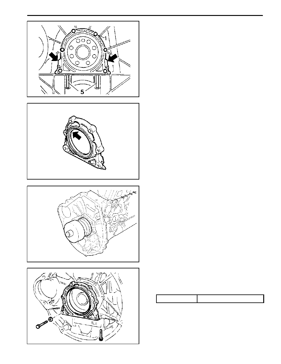
Removal & Installation Procedure
1. Unscrew the bolts (1) and (5) and remove the closing
cover by pulling the rear cover lug (arrows).
Notice: Be careful not to damage the oil pan gasket.
2. Clean the sealing surface of the crankcase and the
rear sealing cover.
3. Check the radial shaft seal and replace it if necessary.
4. Apply the Loctite 573 to the rear cover sealing sur-
face.
5. Apply the engine oil to the dust lip of the radial shaft
seal.
Notice: Do not use the grease.
6. Install the crankshaft rear radial seal and the crank-
shaft sealing rear cover, using crankshaft rear seal in-
staller 601 589 03 43 00.
7. Install the crankshaft sealing rear cover mounting
bolts and remove the crankshaft rear seal installer
601 589 03 43 00.
Installation Notice
Tightening Torque
9 -- 11 NSm (80 -- 97 lb-in)
8. Installation should follow the removal procedure in
the reverse order.
M162 ENGINE MECHANICAL 1B1 -- 35
DAEWOO MY_2000
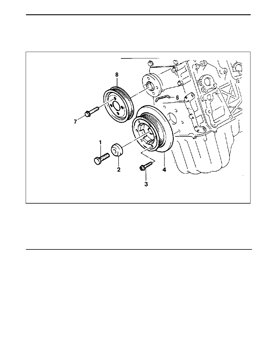
BELT PULLEY AND VIBRATION DAMPER
Preceding Work: Removal of cooling fan and viscous clutch
Removal of fan shroud
Removal of drive belt
1 Vibration Damper Center Bolt (M18 x 50)
1st step 200+20 NSm (148+15 lb-ft)
. . . . . . . . . .
2nd step 90°+10°
2 Vibration Damper Disk
3 Bolt (M6 x 20, 6 pieces)
7.7--9.5 NSm (68.1--84.1 lb-in)
. . . . . . . . . . . . . . .
4 Vibration Damper Assembly
5 Woodruff Key
6 Bolt (M6 x 12, 4 pieces)
9--11 NSm (80--97 lb-in)
. . . . . . . . . . . . . . . . . . . . .
7 Cooling Fan Pulley
1B1 -- 36 M162 ENGINE MECHANICAL
DAEWOO MY_2000
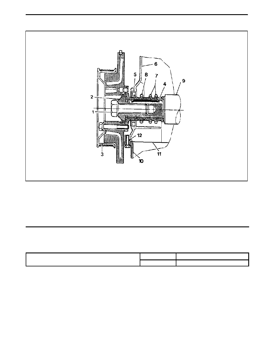
Components
1 Center Bolt (M18 x 50)
2 Center Bolt Washer
3 Vibration Damper and Pulley Assembly
4 Key
5 Crankshaft Front Seal
6 Timing Gear Case Cover
7 Crankshaft Sprocket (Camshaft Driven)
8 Crankshaft Sprocket (Oil pump Driven)
9 Crankshaft
10 Oil Pan
11 Oil Pan Gasket
12 Oil Pan Mounting Bolt (M6 x 22)
Service Data Standard
Permissble Deviation of The Vibration Damper
Radial Runout
0.6 mm
p
Axial Runout
0.6 mm
M162 ENGINE MECHANICAL 1B1 -- 37
DAEWOO MY_2000
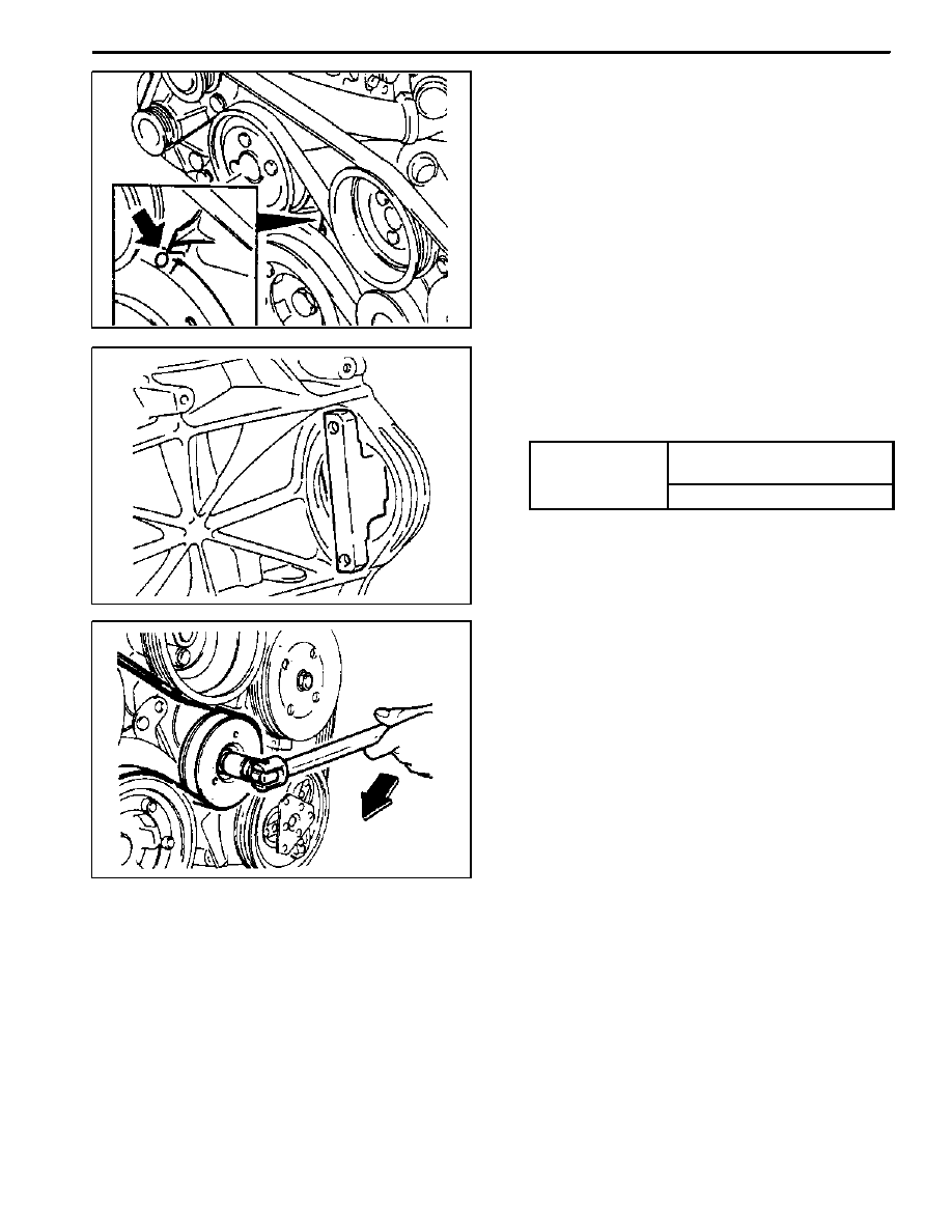
Tools Required
602 589 00 40 00 Engine Lock
Removal & Installation Procedure
1. Adjust the piston of number 1 cylinder to the TDC.
2. Remove the start motor and install the engine lock
602 589 00 40 00 to the flywheel ring gear.
3. Remove the vibration damper center bolt.
Installation Notice
Tightening Torque
1st step: 200 + 20 NSm
(148 + 15 lb-ft)
Tightening Torque
2nd step: 90° + 10°
4. Remove the vibration damper assembly using the
puller.
5. Installation should follow the removal procedure in
the reverse order.
Notice: If possible, don’t separate the vibration damper
and the pulley.
Нет комментариевНе стесняйтесь поделиться с нами вашим ценным мнением.
Текст