SsangYong Korando II (1996-2006 year). Manual — part 12
1B1 -- 14 M162 ENGINE MECHANICAL
DAEWOO MY_2000
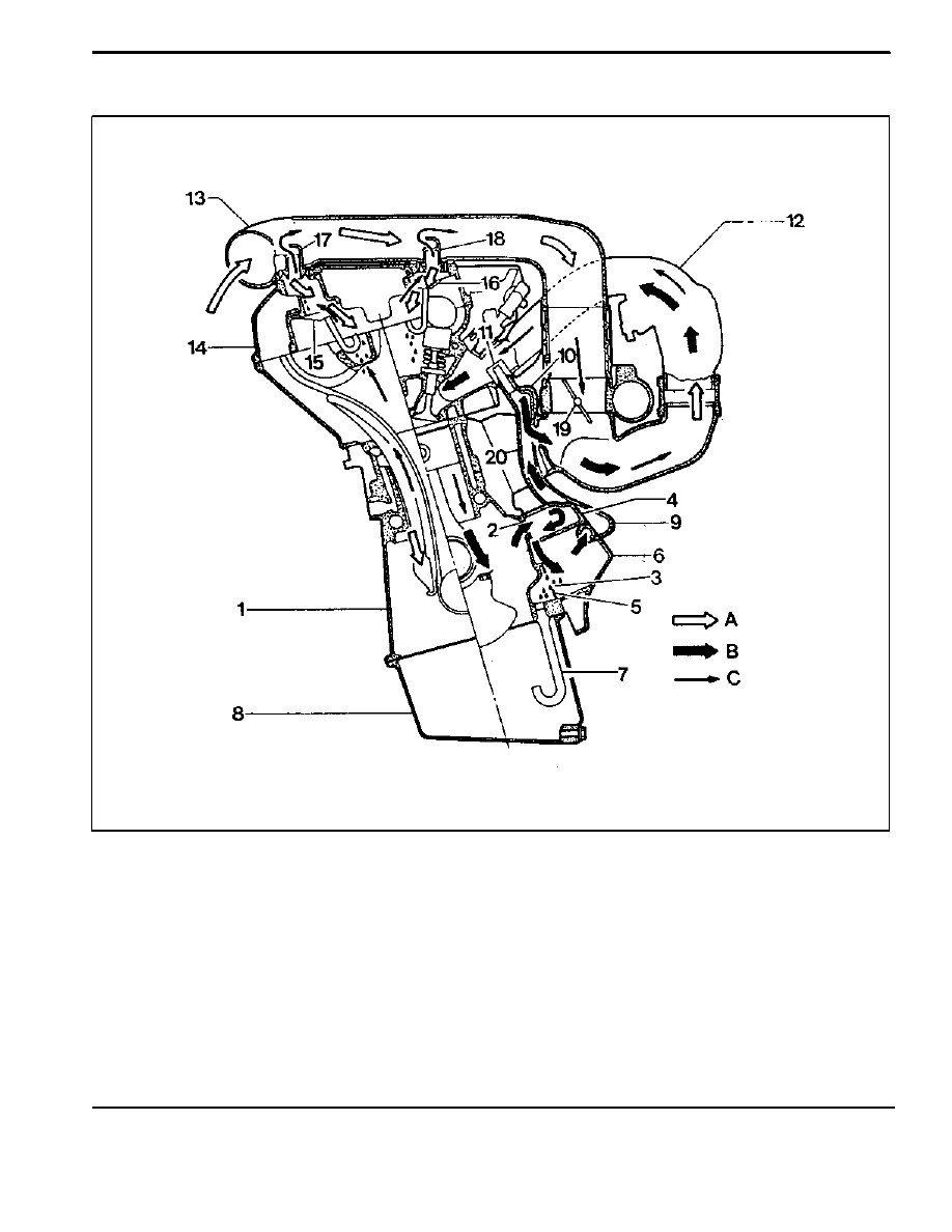
CRANKCASE VENTILATION SYSTEM
1 Crankcase
2 Air Admission Port in Crankcase
3 Oil Drain Port
4 Filter
5 Gasket
6 A/C Bracket
7 Oil Drain Pipe
8 Oil Pan
9 Air Admission Line
10 Vent Line
11 Restriction Hole (Diameter = 2 mm)
12 Intake Manifold
13 Intake Air Duct (Cross Pipe)
14 Cylinder Head Cover
15 Oil Separator
16 Oil Separator
17 Air Admission and Vent Connection
18 Air Admission and Vent Connection
19 Throttle Valve
20 Vent Line
A Fresh Air
B Blowby Gas in Partial Load
C Blowby Gas in Full Load
M162 ENGINE MECHANICAL 1B1 -- 15
DAEWOO MY_2000
Operation at Idling and Mid-Load
D
It show that the throttle valve (19) is closed or very
partially opened and the vacuum pressure in intake
manifold is high.
The blowby gas in the crankcase in partial load flows
into the intake manifold through the vent line (20) af-
ter passing the air conditioner bracket (6) and the fil-
ter (4). The air reentered into the intake manifold will
be dilluted on the flow through the restriction hole (11)
in the vent line (10).
The circulated engine oil is separated at the air condi-
tioner bracket (6) and then returns into the oil pan
through the drain pipe (7).
The vacuum pressure generated at the crankcase
sucks fresh air from intake air line (13) through the air
admission and vent connection (17,18).
The fresh air prevents engine oil from being contami-
nated and the air admission and vent connection
(17,18) is designed to control the rapid pressure
changes in intake air line (13).
Operation at Full-Load
D
The throttle valve (19) is fully opened.
All the blowby gases flow into the intake air duct (13)
after passing through the oil separator (15,16) of the
cylinder head cover (14) when fully loaded. This dil-
luted air will be supplied to the combustion chamber
through the intake manifold (12).
1B1 -- 16 M162 ENGINE MECHANICAL
DAEWOO MY_2000
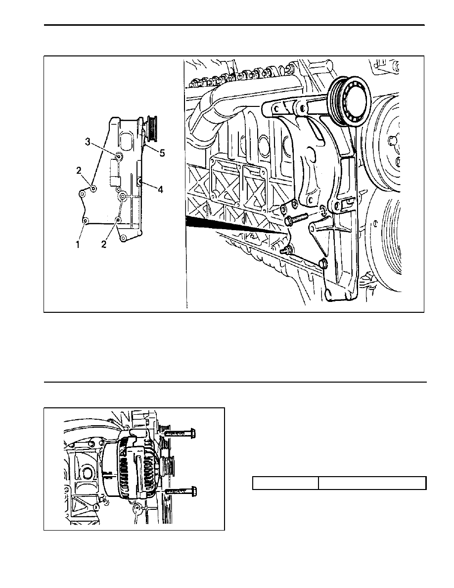
GENERATOR
1 Nut (M8)
22.5--27.5 NSm (16.6--20.3 lb-ft)
. . . . .
2 Bolt (M8 x 30, 3 pieces)
22.5--27.5 NSm (16.6--20.3 lb-ft)
. . . . . . . . . . . . .
3 Bolt (M8 x 40, 1 piece)
22.5--27.5 NSm (16.6--20.3 lb-ft)
. . . . . . . . . . . . .
4 Bolt (M8 x 70, 1 piece)
22.5--27.5 NSm (16.6--20.3 lb-ft)
. . . . . . . . . . . . .
5 Bolt (M8 x 75, 1 piece)
22.5--27.5 NSm (16.6--20.3 lb-ft)
. . . . . . . . . . . . .
Removal & Installation Procedure
1. Remove the drive belt.
2. Remove the generator.
3. Unscrew the generator carrier bolts and remove the
carrier.
Installation Notice
Tightening Torque
25 NSm (18 lb-ft)
4. Installation should follow the removal procedure in
the reverse order.

M162 ENGINE MECHANICAL 1B1 -- 17
DAEWOO MY_2000
ENGINE MOUNT
Removal & Installation Procedure
1. Unscrew the upper engine mount nuts and remove
the engine.
Installation Notice
Tightening Torque
70 NSm (52 lb-ft)
2. Unscrew the lower nuts.
Installation Notice
Tightening Torque
38 NSm (28 lb-ft)
3. Remove the hydraulic engine mounting insulator.
4. Installation should follow the removal procedure in
the reverse order.
Нет комментариевНе стесняйтесь поделиться с нами вашим ценным мнением.
Текст