Isuzu D-Max / Isuzu Rodeo (TFR/TFS). Manual — part 319

AUTOMATIC TRANSMISSION (AW30-40LE) 7A-125
UBS (RHD)
826R200033
TF
826L100002
TRANSMISSION CONTROL MODULE
(TCM)
REMOVAL
Preparation:
Disconnect negative (-) battery cable.
1. Disconnect the TCM harness connectors.
2. Remove fixing nuts (3 pieces) and TCM from the
bracket.
NOTE:
The TCM is fitted under instrument panel of the
driver’s compartment by means of two stud bolts.
INSTALLATION
To install, follow the removal steps in reverse order.
7A-126 AUTOMATIC TRANSMISSION (AW30-40LE)
249RY00011
249RY00012
SHIFT SOLENOID AND LOCK-UP
SOLENOID
REMOVAL
Preparation:
・ Disconnect negative (-) battery cable.
・ Remove the rear sound cover. (UBS)
・ Drain the fluid.
Refer to "ATF REPLACEMENT" in this section.
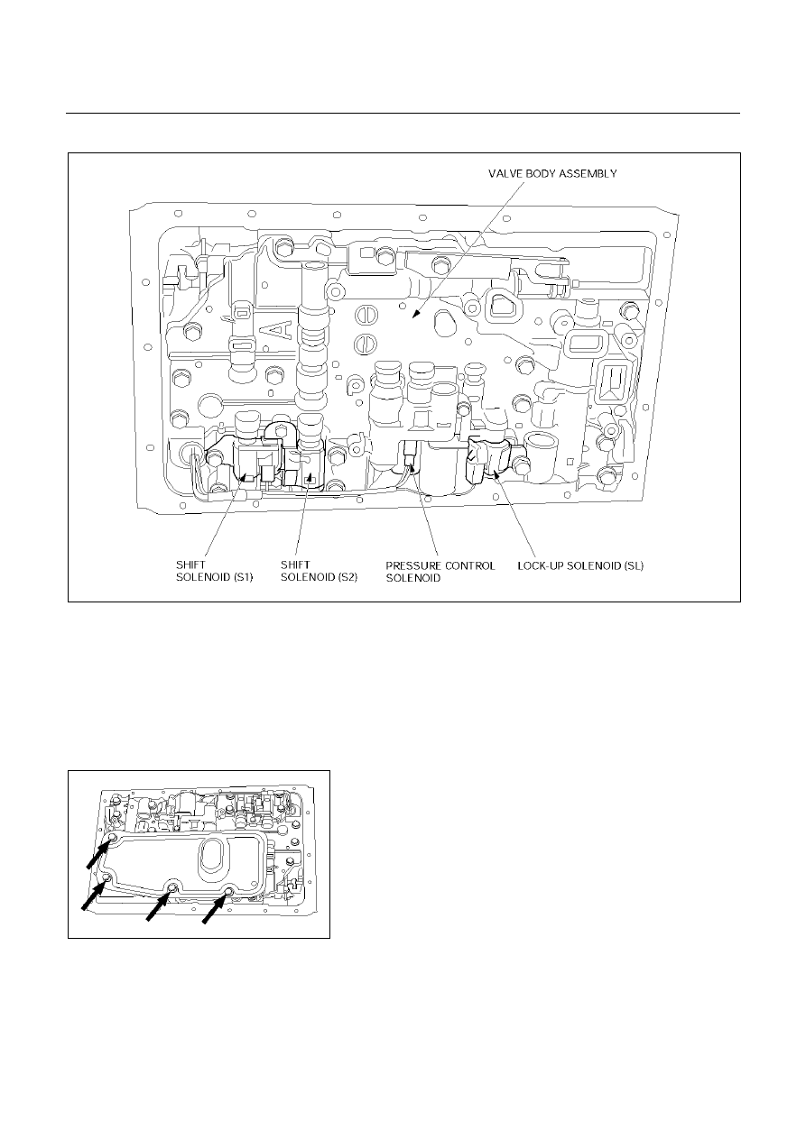
1. Remove the nineteen bolts and oil pan.
2. Remove the oil strainer assembly.
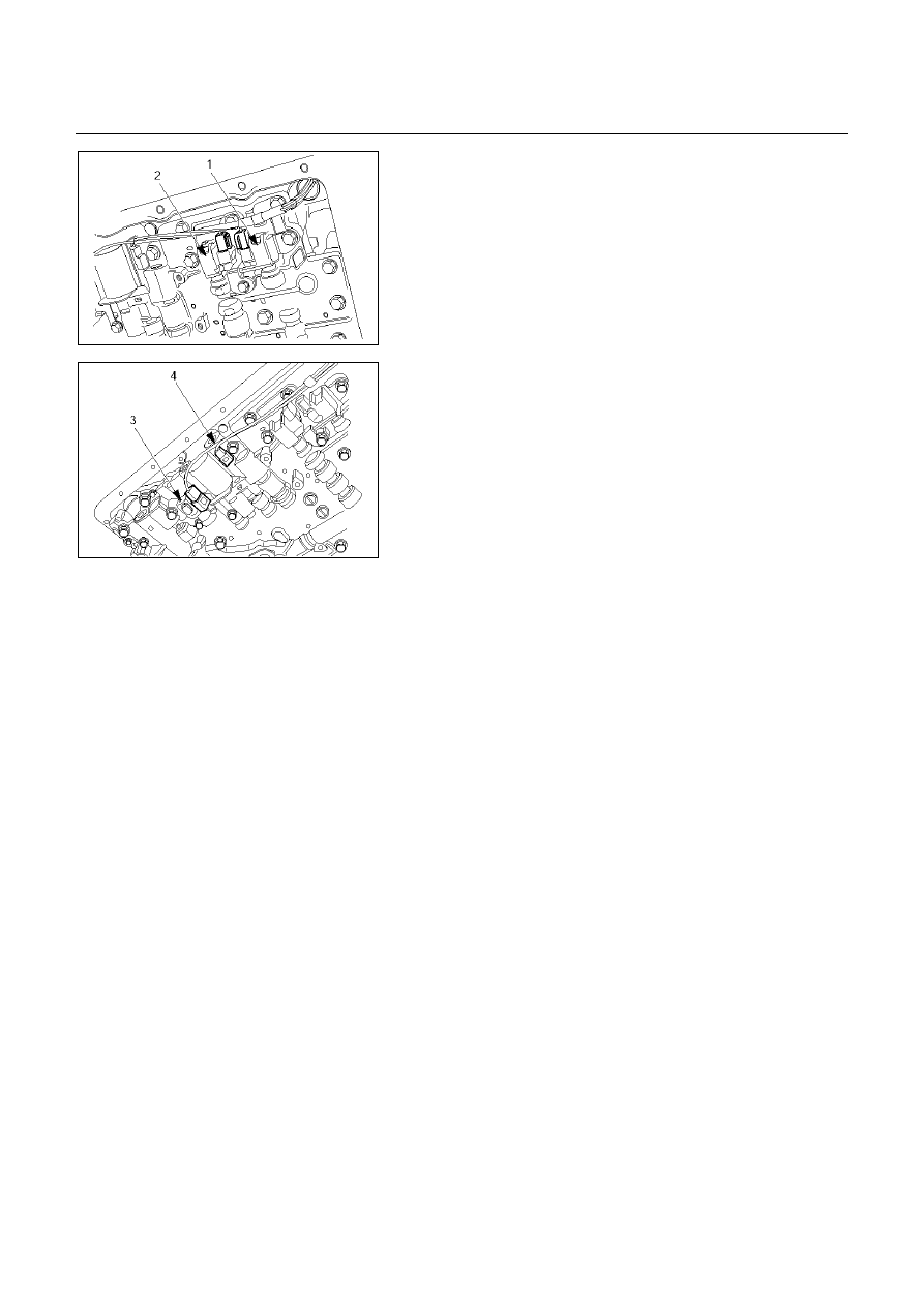
3. Disconnect the solenoid wiring connectors from the
shift solenoid S1(1), S2(2) and lock-up solenoid (3).
4. Remove each retaining bolts and solenoids.
INSTALLATION
To install, follow the removal steps in reverse order noting
the following point;
Torque:
Solenoid S1, S2 bolt −
−
−
− 6.4 N・
・・
・m (0.65 kg・
・・
・m/57 Ib・
・・
・in)
Lock-up solenoid bolt −
−
−
− 10 N・
・・
・m (1.0 kg・
・・
・m/87 Ib・
・・
・in)
AUTOMATIC TRANSMISSION (AW30-40LE) 7A-127
VALVE BODY ASSEMBLY AND PRESSERE CONTOROL SOLENOID
244RY00009
REMOVAL
Preparation:
・ Disconnect negative (-) battery cable.
・ Remove the rear sound cover. (UBS)
・ Drain the fluid.
Refer to "ATF REPLACEMENT" in this section.
1. Remove the nineteen bolts and oil pan.
244RY00003
2. Remove the oil strainer assembly.
3. Disconnect the solenoid wiring connectors from the
solenoids.
4. Remove the twenty bolts from the valve body.
5. Remove the valve body assembly and pressure control
solenoid.
・ When removing valve body assembly from the
transmission case, loosen the solenoid clamp bolt
and remove the pressure control solenoid from the
upper valve body assembly.
Also disconnect the harness connector from the
pressure control solenoid.
7A-128 AUTOMATIC TRANSMISSION (AW30-40LE)
244RY00018
NOTE:
1. Two or more persons are required for removal
and installation of the valve body assembly and
pressure control solenoid.
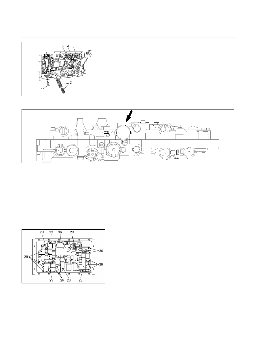
2. The check valve assembly (1) and the C0
accumulator piston springs (2) will fall from the
transmission case during removal of valve body
assembly.
Protect these parts from damage.
The B0 (3), C2 (4), and B2 (5) accumulator piston
and springs may also fall free and must be
protected.
244RY00006
INSTALLATION
To install, follow the removal steps in reverse order noting
the following point;
1. Reinstall the parts removed with the valve body
assembly to their assigned positions in the
transmission case (check valve assembly, C0
accumulator pistons, etc). Install the valve body
assembly to the transmission case.
Refer to “REASSEMBLY OF MAJOR COMPONENTS
(2).”
244R200078
2. Solenoid
clamp
bolt
Torque : 6.4 N・・・・m (0.65 kg・・・・m/57 Ib・・・・in)
3. Valve body fixing bolts
Each bolt location and length (mm) is indicated in the
figure.
Torque : 10 N・・・・m (1.0 kg・・・・m/87 Ib・・・・in)
4. Oil strainer fixing bolts
Torque : 10 N・・・・m (1.0 kg・・・・m/87 Ib・・・・in)
5. Oil
pan
fixing
bolts
Torque : 7.4 N・・・・m (0.75 kg・・・・m/65 Ib・・・・in)
Нет комментариевНе стесняйтесь поделиться с нами вашим ценным мнением.
Текст