Isuzu D-Max / Isuzu Rodeo (TFR/TFS). Manual — part 554
6A – 54 ENGINE MECHANICAL
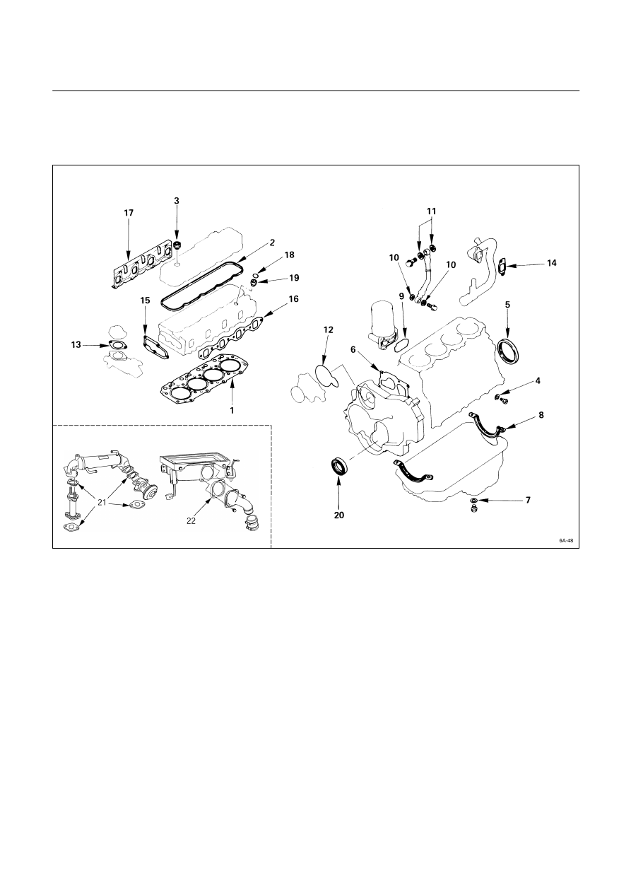
ENGINE REPAIR KIT
All of the numbered parts listed below are included in the Engine Repair Kit.
The gaskets marked with an asterisk (*) are also included in the Top Overhaul Kit.
* 1.
Cylinder head gasket
12.
Water pump O-ring
* 2.
Head cover gasket
*
13.
Water outlet pipe gasket
* 3.
Head cover cap nut gasket
*
14.
Intake pipe gasket
4.
Drain cock gasket
15.
Thermostat housing gasket
5.
Crankshaft rear oil seal
*
16.
Intake manifold gasket
6.
Gear case gasket
*
17.
Exhaust manifold gasket
7.
Oil pan drain plug gasket
*
18.
Nozzle holder O-ring
8.
Oil pan gasket
*
19.
Nozzle holder gasket
9.
Oil filter gasket
20.
Crankshaft front oil seal
10.
Joint bolt gasket
21.
EGR Cooler gasket (4JA1TC
only)
11.
Vacuum pump gasket
22.
Inter cooler outlet pipe gasket
(4JA1TC, 4JH1TC only)

ENGINE MECHANICAL 6A – 55
ENGINE OVERHAUL
REMOVAL
EXTERNAL PARTS
These removal steps are based on the 4JB1T engine.
The triangle (
J
) mark indicates the important operations.
Removal Steps
1.
Cooling fan drive belt
16.
Turbocharger heat protector
2.
Cooling fan pulley
17.
Exhaust adaptor
3.
Heater pipe (rear side)
18.
Turbocharger oil return pipe
4.
Oil level gauge and guide tube
19.
Turbocharger oil feed pipe
5.
Starter motor
J
20. Turbocharger
6.
Water drain cock
21.
Exhaust manifold heat protector
7.
Oil pressure warning switch and
22.
Oil cooler with Oil filter
nipple
23.
Exhaust
manifold
8.
Engine mounting bracket
24.
Compressor bracket
J
9.
Intake manifold
25.
Generator bracket
J
10.
Fuel injection pipe with clip
26.
Power steering oil pump
11.
Fuel leak off pipe
27.
Vacuum pipe
12.
Injection pump
13.
Compressor
14.
Generator and adjusting plate
15.
Water inlet pipe

6A – 56 ENGINE MECHANICAL
Important Operations
9. Intake
Manifold
1) Disconnect the PCV hose from the cylinder head
cover.
2) Disconnect the intake duct and intake rubber hose
from the turbocharger.
3) Remove the upper intake manifold the lower intake
manifold with intake duct, and the PCV hose.
10. Fuel Injection Pipe with Clip
1) Loosen the injection pipe sleeve nuts at the delivery
valve side
Q
and injection nozzle side.
Do not apply excessive force to the injection pipes.
2) Loosen the injection pipe clips
R
.
3) Remove the injection pipes
S
.
Note:
Plug the delivery holder ports with the shipping caps
to prevent the entry of foreign material.
20. Turbocharger
Plug the turbocharger body oil ports after removing the
turbocharger assembly to prevent the entry of foreign
material.

ENGINE MECHANICAL 6A – 57
INTERNAL PARTS
MAJOR COMPONENTS
Disassembly Steps-1
1.
Water bypass pipe
5.
Glow plug and glow plug
2.
Thermostat housing with thermo
connector
switch
J
6.
Rocker arm shaft and rocker
3.
Cylinder head cover
arm
J
4.
Injection nozzle and Injection
7.
Push rod
nozzle
holder
J
8.
Cylinder head
4a. Injection nozzle (4JG2T)
9.
Cylinder head gasket
4b. Injection nozzle and Injection
Nozzle holder (4JA1TC, 4JH1TC)
025L200001
Нет комментариевНе стесняйтесь поделиться с нами вашим ценным мнением.
Текст