Isuzu KB P190. Manual — part 1439

9A1-74 RESTRAINT CONTROL SYSTEM
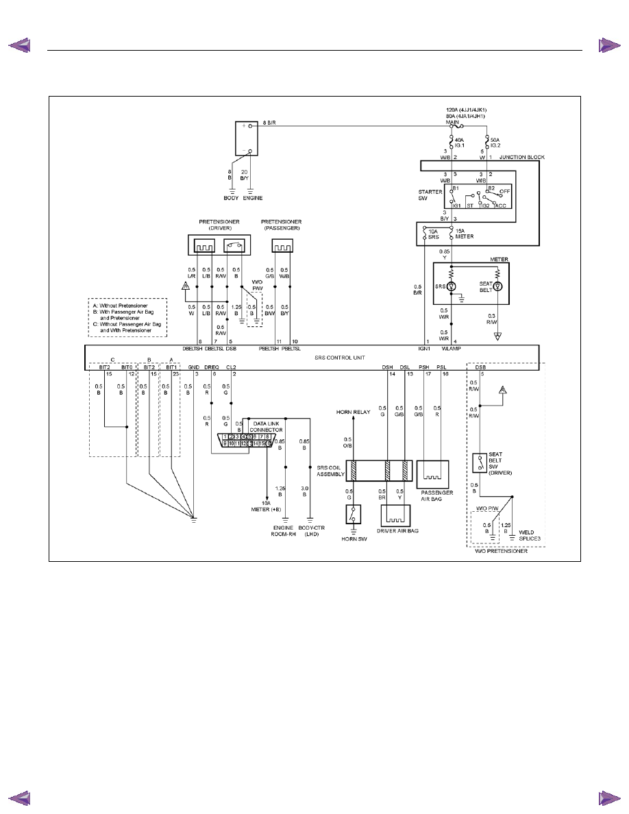
DTC B0063 (Flash Code 63) Battery Voltage Too Low
Step Action
Yes
No
1
Was the “SRS Diagnostic System Check” performed?
Go to Step 2
Go to the “SRS
Diagnostic System
Check”
2
1. Ignition switch is at “LOCK”.
2. Disconnect the SRS control unit.
3. Ignition switch “ON”.
4. Measure voltage on SRS control unit harness connector from
terminal “1” to terminal “3” (ground).
Is voltage on terminal “1” above 10.6V?
Go to Step 5
Go to Step 3
3
1. Ignition switch is at “LOCK”.
2. Remove and inspect “SRS” fuse to the “Ignition 1”.
Is fuse good?
Go to Step 4
Replace the "SRS"
fuse.
Go to Step 6
4
1. Ignition switch is at “LOCK”.
2. Measure resistance from "SRS" fusel to SRS control unit
harness connector terminal “1”.
Is resistance 5.0 ohms or less?
Inspect the
Charging System.
Refer to the
"Engine Electrical"
section.
Go to Step 6
Replace the SRS
harness.
Go to Step 6
5
1. Remove the "SRS" fuse.
2. Measure the resistance on the SRS control unit harness
connector as follow.
From terminals "1" to "3" and "23" (ground) (without the
pretensioner)
From terminals "1" to "3" and "15" (ground) (with the
pretensioner and the passenger air bag)
From terminals "1" to "3", "12" and "15" (ground) (with
the pretensioner and without the passenger air bag)
Does 5-8840-0366-0 display “OL” (Infinite)?
Ignition switch is at
“LOCK”.
Replace the SRS
control unit.
Go to Step 6
Replace SRS
Harness.
Go to Step 6
6
1. Reconnect all the components and ensure all components
are properly mounted.
2. Clear diagnostic trouble codes.
Is this step finished?
Go to the “SRS
Diagnostic system
Check”
―
RESTRAINT CONTROL SYSTEM 9A1-75
DTC B0071 (Flash Code 71) SRS Control Unit Internal Fault
RTW79ALF000301
Circuit Description
DTC B0071 is an indication of a potential internal SRS
control unit malfunction and will set if any of the
following conditions are detected:
1) Microprocessor energy reverse time failure.
2) EEPROM read / write failure.
3) ROM check sum.
4) Calibration check sum fault.
5) Inflators reserve voltage low.
6) Inflators electronic sensor active signal not detected
during commanded deployment.
7) QSDD (High-side/Low-side) FET failure.
8) Frontal accelerometer failure.
9) Phase lock loop lost lock.
10) QSDD communication fault.
DTC Will Set When
Any of the above indicated malfunctions are detected by
the SRS control unit. The malfunctions described
above are tested mainly during “Continuous Monitoring”
and some are run each ignition cycle.
Action Taken
SRS control unit turns “ON” the “SRS” warning lamp
and sets a diagnostic trouble code.
DTC Will Clear When
The SRS control unit is replaced.
9A1-76 RESTRAINT CONTROL SYSTEM
DTC B0071 (Flash Code 71) SRS Control Unit Internal Fault
WARNING: DURING SERVICE PROCEDURES. BE VERY CAREFUL WHEN HANDLING A SRS CONTROL UNIT.
NEVER STRIKE OR JAR THE SRS CONTROL UNIT. NEVER POWER UP THE SRS WHEN THE SRS CONTROL
UNIT IS NOT RIGIDLY ATTACHED TO THE VEHICLE. ALL SRS CONTROL UNIT AND MOUNTING BRACKET
FASTENERS MUST BE CAREFULLY TORQUED AND THE ARROW MUST BE POINTING TOWARD THE FRONT
OF THE VEHICLE TO ENSURE PROPER OPERATION OF THE SRS. THE SRS CONTROL UNIT COULD BE
ACTIVATED WHEN POWERED WHILE NOT RIGIDLY ATTACHED TO THE VEHICLE WHICH COULD CAUSE
DEPLOYMENT AND RESULT IN PERSONAL INJURY.
CAUTION: If DTC B0071 can not be cleared by Tech2, it is necessary to replace the SRS control unit.
Step Action
Yes
No
1
Was the “SRS Diagnostic System Check” performed?
Ignition switch
“LOCK”.
Replace SRS
control unit.
Repeat the “SRS
Diagnostic System
Check”
Go to the “SRS
Diagnostic System
Check”

CAB 10-1
SECTION 10
CAB
TABLE OF CONTENTS
PAGE
Windshield . . . . . . . . . . . . . . . . . . . . . . . . . . . . . . . 10- 2
Rear Window Assembly. . . . . . . . . . . . . . . . . . . . . . . . . 10- 6
Front Door Assembly . . . . . . . . . . . . . . . . . . . . . . . . . . 10- 9
Rear Door Assembly (Crew Cab) . . . . . . . . . . . . . . . . . . . . . . 10- 19
Instrument Panel . . . . . . . . . . . . . . . . . . . . . . . . . . . ... 10- 27
Floor Console . . . . . . . . . . . . . . . . . . . . . . . . . . . . . 10- 35
Console Box (Without Floor Console). . . . . . . . . . . . . . . . . . . . 10- 39
Headlining . . . . . . . . . . . . . . . . . . . . . . . . . . . . . . .. 10- 40
Interior Trim Panels. . . . . . . . . . . . . . . . . . . . . . . . . . ... 10- 45
Fuel Filler Lid Opener Lever/Cable . . . . . . . . . . . . . . . . . . . . .. 10- 56
Quarter Glass (Extend Cab). . . . . . . . . . . . . . . . . . . . . . . .. 10- 71
Font Seat . . . . . . . . . . . . . . . . . . . . . . . . . . . . . . . 10- 72
Rear Seat (Crew Cab) . . . . . . . . . . . . . . . . . . . . . . . . . . 10- 74
Jump Seat (Extend Cab) . . . . . . . . . . . . . . . . . . . . . . . . ... 10- 75
Front Seat Belt . . . . . . . . . . . . . . . . . . . . . . . . . . . . ... 10- 76
Rear Seat Belt (Crew Cab) . . . . . . . . . . . . . . . . . . . . . . . . 10- 80
Rear Seat Belt (Extend Cab) . . . . . . . . . . . . . . . . . . . . . . . . 10- 84
Front Wheel Extension (A type) . . . . . . . . . . . . . . . . . . . . . ... 10- 87
Front Wheel Extension (B type) . . . . . . . . . . . . . . . . . . . . . ... 10- 88
Rear Wheel Extension (A type). . . . . . . . . . . . . . . . . . . . . . . 10- 89
Rear Wheel Extension (B type). . . . . . . . . . . . . . . . . . . . . . . 10- 90
Tail Gate Assembly . . . . . . . . . . . . . . . . . . . . . . . . . . ... 10- 91
ISUZU KB P190 2007
Нет комментариевНе стесняйтесь поделиться с нами вашим ценным мнением.
Текст