Isuzu KB P190. Manual — part 1440
10-2 CAB
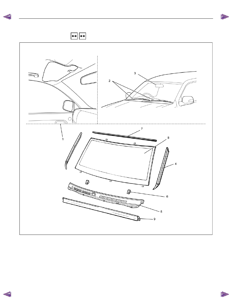
WINDSHIELD
REMOVAL AND INSTALLATION
This illustration is based on RHD model
RTW7A0LF001201
Removal Steps
1. Interior trim panels (Front side)
/Headlining/Instrument panel assembly
2. Wiper arm assembly
▲ 3. Room mirror
4. Side molding
5. Vent cowl cover
6. Windshield stopper
7. Upper molding
▲ 8. Windshield
9. Engine hood rear seal
Installation Steps
▲ 9. Engine hood rear seal
▲ 8. Windshield
7. Upper molding
6. Windshield stopper
5. Vent cowl cover
4. Side molding
3. Room mirror
▲ 2. Wiper arm assembly
1. Interior trim panels (Front side)
/Headlining/Instrument panel assembly
CAB 10-3
RUW5A0SH002901
Important Operations - Removal
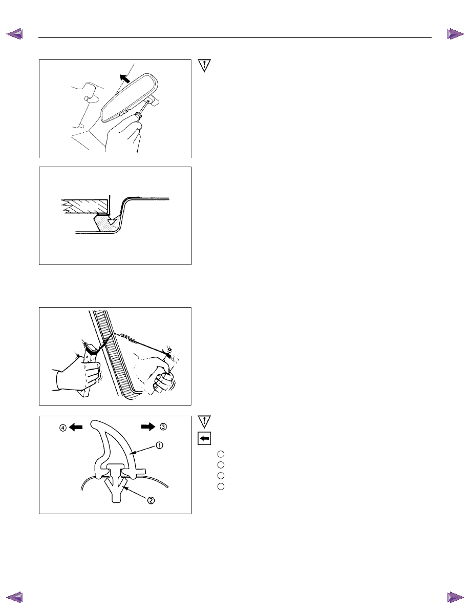
3. Room Mirror
Remove the screw and pull the room mirror to the upper side.
8. Windshield
Remove the windshield, carefully following the steps listed
below:
1) Use a knife to cut through part of the adhesive caulking
material.
2) Secure one end of a piece of steel piano wire (0.02 inches
in diameter) to a piece of wood that can serve as a handle.
3) Use a pair of needle nose pliers to insert the other end of
the piano wire through the adhesive caulking material at the
edge of the windshield.
4) Secure the other end of the piano wire to another piece of
wood.
5) With the aid of an assistant, carefully move the piano wire
with a sawing motion to cut through the adhesive caulking
material around the entire circumference of the windshield.
6) Lift the windshield from the body.
7) Clean any remaining adhesive caulking material from the
area of the body which holds the windshield.
8) Use a soft rag and unleaded gasoline to wipe off any
adhesive remaining on the windshield.
Important Operations - Installation
9. Engine Hood Rear Seal
Install the engine hood rear seal as shown in the illustration.
1
: Seal
2
: Clip
3
: Rear (windshield side)
4
: Front
10-4 CAB
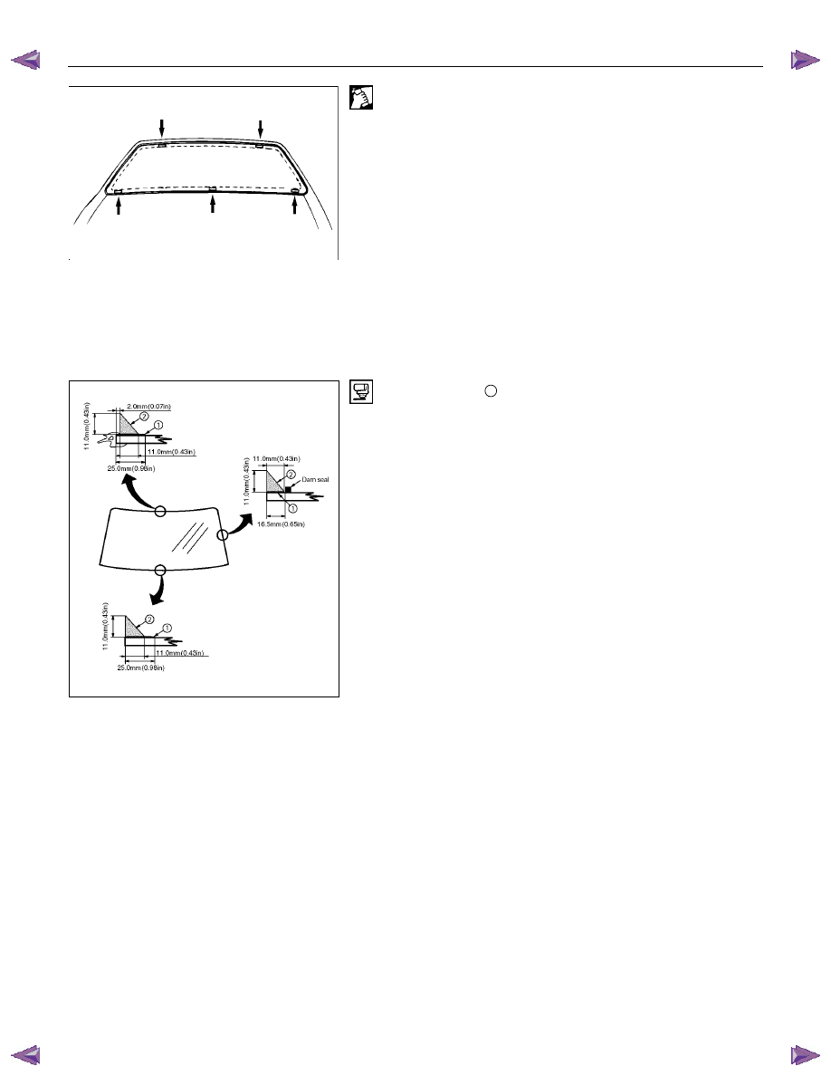
8. Windshield
1) Clean the windshield bonding surface.
2) Use a soft rag and unleaded gasoline to wipe off any
adhesive remaining on the body.
3) Mount the body windshield as shown in the illustration.
Attach spacers at five locations.
• Always use new spacers.
4) Install the windshield upper molding.
• Peel off the tear-away paper from the windshield upper
molding, and start applying it with one end of the
windshield and cut away the surplus at the other end of
the windshield for length adjustment.
• Always use new upper molding.
5) Temporarily install the windshield support.
6) Apply primer
1
Sunstar #435-98 or equivalent to the body
side bonding surface. The primer should extend at least 25
mm (0.98 in).
Apply primer Sunstar #435-40 or equivalent to the
windshield side bonding surface.
The primer should extend 16.5 mm (0.65 in) and 25 mm
(0.98 in) from end of the windshield.
CAB 10-5
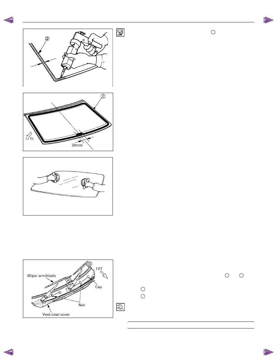
7) Apply the windshield sealing adhesive
2
.
If you are using an air gun, air pressure should be
maintained at 147 - 294 kPa.
After drying the primer completely, apply a sealing adhesive
(Sunstar #557 or equivalent) along the edge of the
windshield so that the sealing adhesive has a 20 mm (0.79
in) junction at the middle of the base of the windshield.
Note :
Open time (1 min. or more) should be set after application
of the primer.
Bonding shall be done within 5 minutes after the sealing
adhesive has been applied.
8) Adjust the setting of the windshield with suction discs.
Set the windshield with sealing adhesive applied to the
entire circumference on the body panel. Specifically, adjust
the windshield support with the upper molding making
contact with the body panel, press the windshield, and
tighten the windshield support.
9) Use unleaded gasoline and a soft cloth to wipe away any
excess adhesive.
Cure the bonding at a temperature of 20 - 30
°C (68 - 86°F)
for twenty-four hours.
Check that the windshield does not leak water.
2. Wiper Arm Assembly
• Set the wiper arm/blade so that the tips of both blades
are positioned to the specified value of
A
and
B
from
the upper edge of the cowl cover as shown in the figure.
A
40 mm (1.57 in)
B
52 mm (2.05 in)
• Tighten the wiper arm assembly fixing nuts to the
specified torque.
Torque N
⋅m (kgf⋅m/lb⋅ft)
31 (3.2/23)
Нет комментариевНе стесняйтесь поделиться с нами вашим ценным мнением.
Текст