Isuzu KB P190. Manual — part 1438
9A1-70 RESTRAINT CONTROL SYSTEM
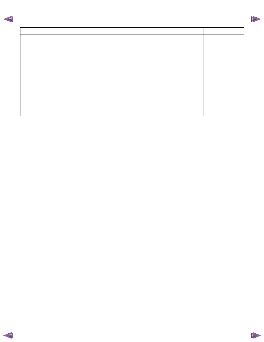
Step Action
Yes
No
8
1. Ignition switch is at “LOCK”.
2. Measure the resistance from the instrument meter cluster
harness connector "SRS" warning lamp circuit terminal to the
SRS control unit harness connector terminal “4”.
Is the resistance 5.0 ohms or less?
Go to Step 9
Replace the SRS
harness.
Go to Step 10
9
1. Disconnect the instrument meter cluster harness connector.
2. Measure the resistance from the "METER" fuse to the
instrument meter cluster harness connector "SRS" warning
lamp power supply circuit terminal.
Is the resistance 5.0 ohms or less?
Service instrument
meter cluster.
Install instrument
meter cluster.
Go to Step 10
Replace the "SRS"
warning lamp
power supply
circuit harness.
Go to Step 10
10
1. Reconnect all components and ensure all components are
properly mounted.
2. Clear the diagnostic trouble codes.
Is this step finished?
Go to the “SRS
Diagnostic System
Check”
―

RESTRAINT CONTROL SYSTEM 9A1-71
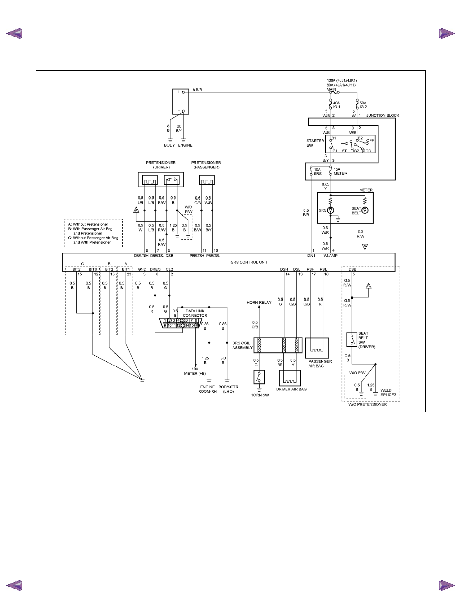
DTC B0062 (Flash Code 62) Battery Voltage Too High
RTW79ALF000301
Circuit Description
When the ignition switch is turned “ON", the SRS
control unit judge to "Ignition 1" voltage is normal or not.
DTC Will Set When
The "Ignition 1" voltage is above 21.4V.
Action Taken
The SRS control unit turns “ON” the “SRS” warning
lamp and sets a diagnostic trouble code.
DTC Will Clear When
The “Ignition 1" voltage comes to below 16.5V.
DTC Chart Test Description
Number(s) below refer to circled number(s) on the
diagnostic chart.
2. This test determines whether the SRS control unit is
malfunctioning.

9A1-72 RESTRAINT CONTROL SYSTEM
DTC B0062 (Flash Code 62) Battery Voltage Too High
Step Action
Yes
No
1
Was the “SRS Diagnostic System Check” performed?
Go to Step 2
Go to the “SRS
Diagnostic System
Check”
2
1. Ignition switch is at “LOCK”.
2. Disconnect the SRS control unit.
3. Ignition switch “ON”.
4. Measure voltage on SRS control unit harness connector from
terminal “1” to terminal “3” (ground).
Is voltage on terminal “1” below 16.5V?
Ignition switch is at
“LOCK”.
Replace the SRS
control unit.
Go to Step 3
Inspect the
Charging System.
Refer to the
"Engine Electrical"
section.
Go to Step 3
3
1. Reconnect all the components and ensure all components
are properly mounted.
2. Clear diagnostic trouble codes.
Is this step finished?
Go to the “SRS
Diagnostic system
Check”
―
RESTRAINT CONTROL SYSTEM 9A1-73
DTC B0063 (Flash Code 63) Battery Voltage Too Low
RTW79ALF000301
Circuit Description
When the ignition switch is turned “ON", the SRS
control unit judge to "Ignition 1" voltage is normal or not.
DTC Will Set When
The "Ignition 1" voltage is below 7.2V.
Action Taken
The SRS control unit turns “ON” the “SRS” warning
lamp and sets a diagnostic trouble code.
DTC Will Clear When
The “Ignition 1" voltage comes to above 10.6V.
DTC Chart Test Description
Number(s) below refer to circled number(s) on the
diagnostic chart.
4. This test determines whether the malfunction is in
the “Ignition 1” circuit.
5. This test determines whether the malfunction is in
the “Ignition 1” circuit.
Нет комментариевНе стесняйтесь поделиться с нами вашим ценным мнением.
Текст