Isuzu KB P190. Manual — part 755
Engine Mechanical – V6
Page 6A1–243
Page 6A1–243
22
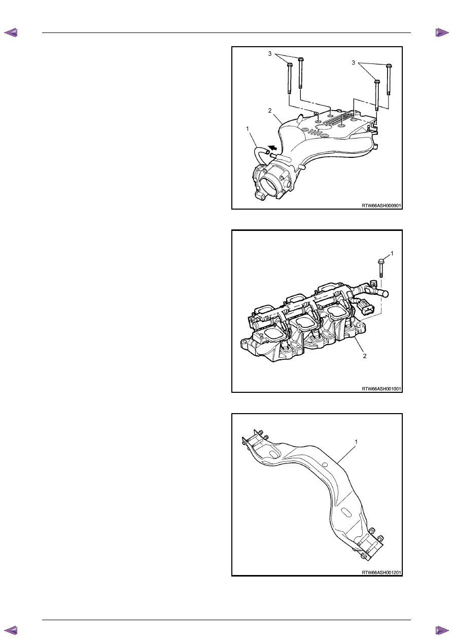
Disconnect the EVAP valve outlet tube, (1) from the
upper intake manifold (2).
23
Remove the four long bolts, (3) attaching the upper
intake manifold, (2) to the cylinder heads and lower
intake manifold.
Figure 6A1 – 414
23
Remove the six bolts, (1) attaching the lower intake
manifold (2), then remove the manifold from the
engine.
24
Remove the following from the engine and engine
compartment :
•
Lower intake manifold to cylinder head gasket
•
The Heater hose
•
The Air Cleaner assembly
Figure 6A1 – 415
25
Remove the transmission support (1).
26
Remove the front and rear propeller shafts, (4WD
Only), refer to
Section 4C1 Front Wheel Drive
and
Section 4C2 Drive Line
(For 4WD Vehicles).
27
Remove the front torsion bar springs, refer to
Section 3C Suspension
.
Figure 6A1 – 416
Engine Mechanical – V6
Page 6A1–244
Page 6A1–244
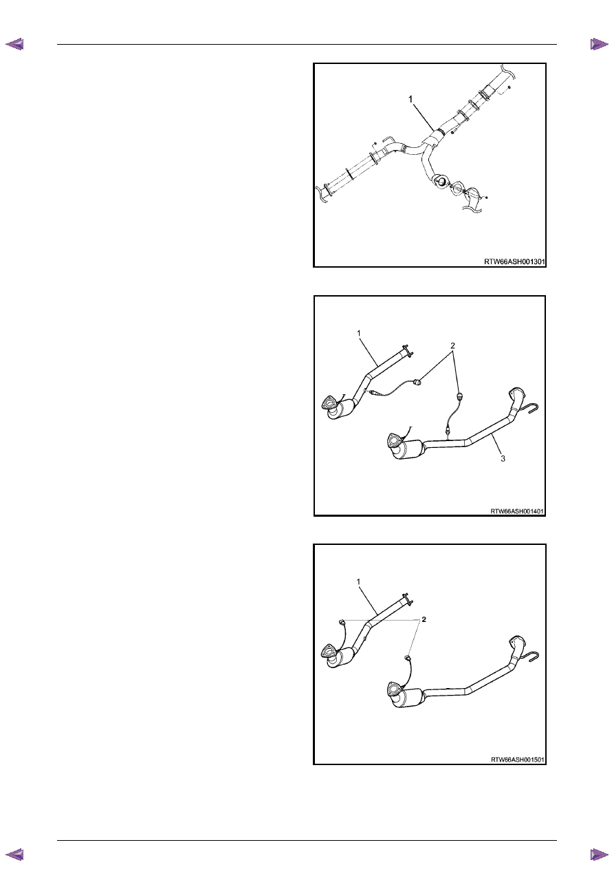
28
Remove the centre exhaust pipe (1), refer to
Section 6F Exhaust System - V6
.
Figure 6A1 – 417
29
Disconnect the two post-catalytic converter oxygen
sensor wiring harness connectors, 1 each bank.
Figure 6A1 – 418
30
Disconnect the two pre-catalytic converter oxygen
sensor wiring harness connectors, 1 each bank.
31
Remove the front exhaust flange nuts, three each
bank.
32
Remove the front left-hand exhaust pipe from the
rubber mount.
33
Remove the front exhaust pipes from the vehicle, for
further information, refer to
Section 6F Exhaust
System - V6
.
Figure 6A1 – 419
34
Remove the transfer case from the vehicle (4WD Only), refer to
Section 7D Transfer Case and Adaptor Housing
.

Engine Mechanical – V6
Page 6A1–245
Page 6A1–245
35
Disconnect the harness connector from the transmission, refer to
Section 7B1 Manual Transmission – V6
or
Section 7C1, Section 7C2, Section 7C3
or
Section 7C4
for automatic transmission.
36
Remove the left-hand side exhaust manifold upper
heat shield (1), (Automatic transmission only).
Figure 6A1 – 420
37
Progressively loosen the seven exhaust manifold
attaching bolts (2), working from the outside to the
centre and then remove the bolts.
38
Manoeuvre the exhaust manifold (3), away from the
cylinder head.
39
Remove and discard the exhaust manifold to cylinder
head gasket.
Figure 6A1 – 421
40
Remove the engine oil level indicator assembly (1),
(automatic transmission only).
41
Remove the left-hand side exhaust manifold,
(automatic transmission only).
Figure 6A1 – 422
Engine Mechanical – V6
Page 6A1–246
Page 6A1–246
Figure 6A1 – 423
Figure 6A1 – 424
42
Fit the engine lifting brackets (1), (EN–46114) and attach the engine hoist, raise the engine to take the weight off
the engine mounts.
Engine Lift Bracket Attaching Bolt
torque specification
. . . . . . . . . . . . . . . .58.0 – 72.0.0 Nm
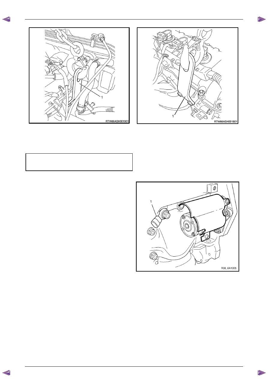
43
Remove the left-hand side knock sensor (1).
Figure 6A1 – 425
N O T E
Removal or the starter motor is only required for
vehicles with an Automatic Transmission.
Нет комментариевНе стесняйтесь поделиться с нами вашим ценным мнением.
Текст