Isuzu KB P190. Manual — part 754
Engine Mechanical – V6
Page 6A1–239
Page 6A1–239
4
Major Service Operations
A T T E N T I O N
The V6 engine is a combination of numerous components, containing machined, honed, polished and lapped
surfaces manufactured on the latest, high technology production equipment. Many of the components
contain tolerances measured in thousandths of a millimetre. Consequently, when any engine component is to
be serviced, care and cleanliness are extremely important.
Prior to re-assembly of the V6 engine, all components must be cleaned and inspected in accordance with the
relevant procedures throughout this section, and replaced or repaired where required.
In addition to cleaning and inspecting components, a liberal coating of engine oil should be applied to friction
surfaces during assembly to protect and lubricate the surfaces on initial operation.
When performing any service operation contained in this Section, it should be understood that correct
cleaning and protection of machined surfaces and friction areas is part of the repair procedure. This is
considered standard workshop practice, even if not specifically stated. Torque values must be used as
specified during reassembly to ensure correct retention of all components.
Through out this section, fastener torque wrench specifications may be accompanied with the following
identification marks:
■
Fasteners must be replaced after loosening.
Fasteners either have micro encapsulated sealant applied or incorporate a mechanical thread lock and
should only be re-used once. If in doubt, replacement is recommended.
If one of these identification marks is present alongside a fastener torque wrench specification, the
recommendation regarding that fastener must be adhered to.
4.1 Engine
Removal
CAUTION
• Allow the engine to cool to at least 50° C,
before attempting fastener removal.
• As aluminium has a greater rate of thermal
expansion than that of cast iron,
aluminium bolt hole threads will change
dimension to a larger extent than cast iron
bolt threads.
• If a bolt or other threaded component is
removed before the engine is allowed to
cool to at least 50
° C, threads could be
pulled from the cylinder block or cylinder
head.
• Do not use impact tools to remove bolts
during engine disassembly. While this may
be common practice with cast iron engine
components, use of these tools is likely to
pull the aluminium threads in the cylinder
block or head of this engine.
Engine Mechanical – V6
Page 6A1–240
Page 6A1–240
Remove
1
Remove the skid plate.
2
Drain the radiator coolant, refer to
Section 6B1 Engine Cooling – V6
.
3
Disconnect the battery negative and positive terminal, refer to
Section 8A Electrical Body & Chassis
.
4
Remove the battery from the vehicle.
5
Depressurise the fuel system pressure, refer to
Section 6C Fuel System – V6
.
6
Make alignment marks on the bonnet and hinges in order to return the bonnet to the exact original position.
7
Remove the bonnet, refer to
Section 2B Sheet Metal
.
8
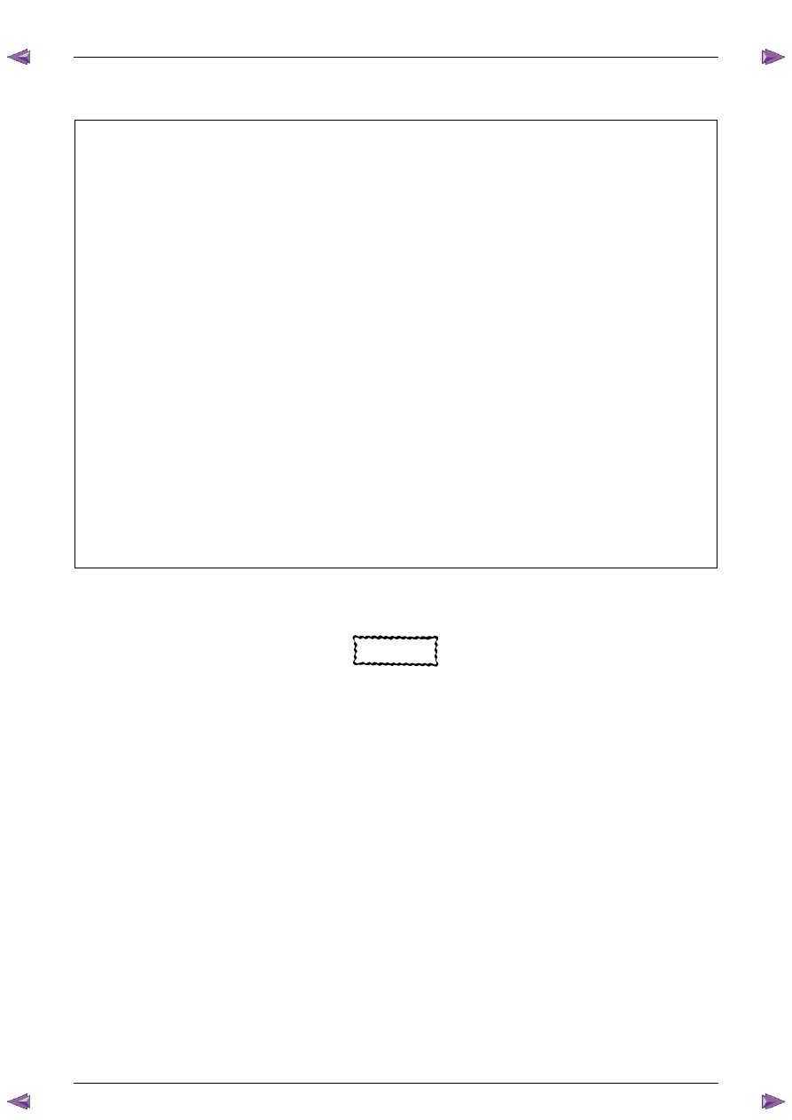
Remove the rubber hose (2) and air duct (1).
Figure 6A1 – 407
9
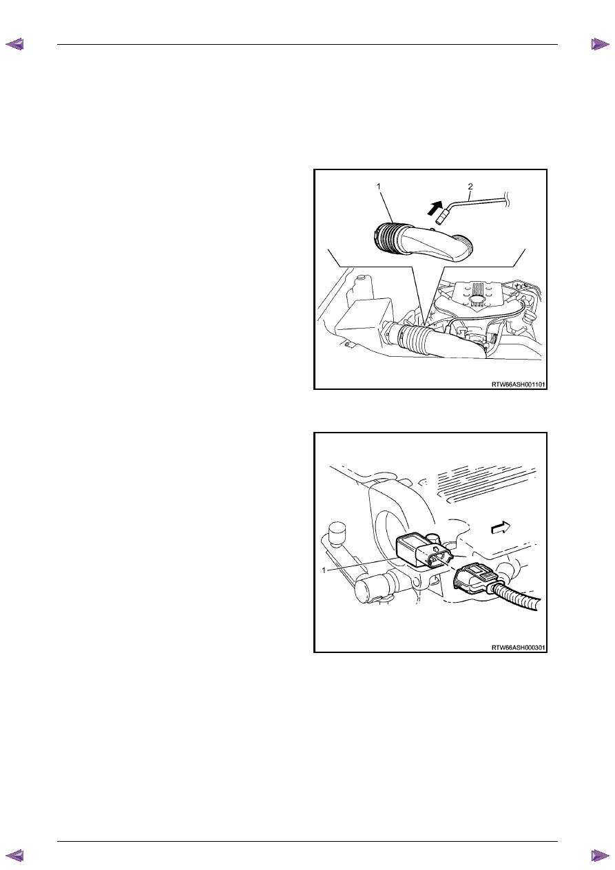
Disconnect the barometric sensor connector (1).
Figure 6A1 – 408
Engine Mechanical – V6
Page 6A1–241
Page 6A1–241
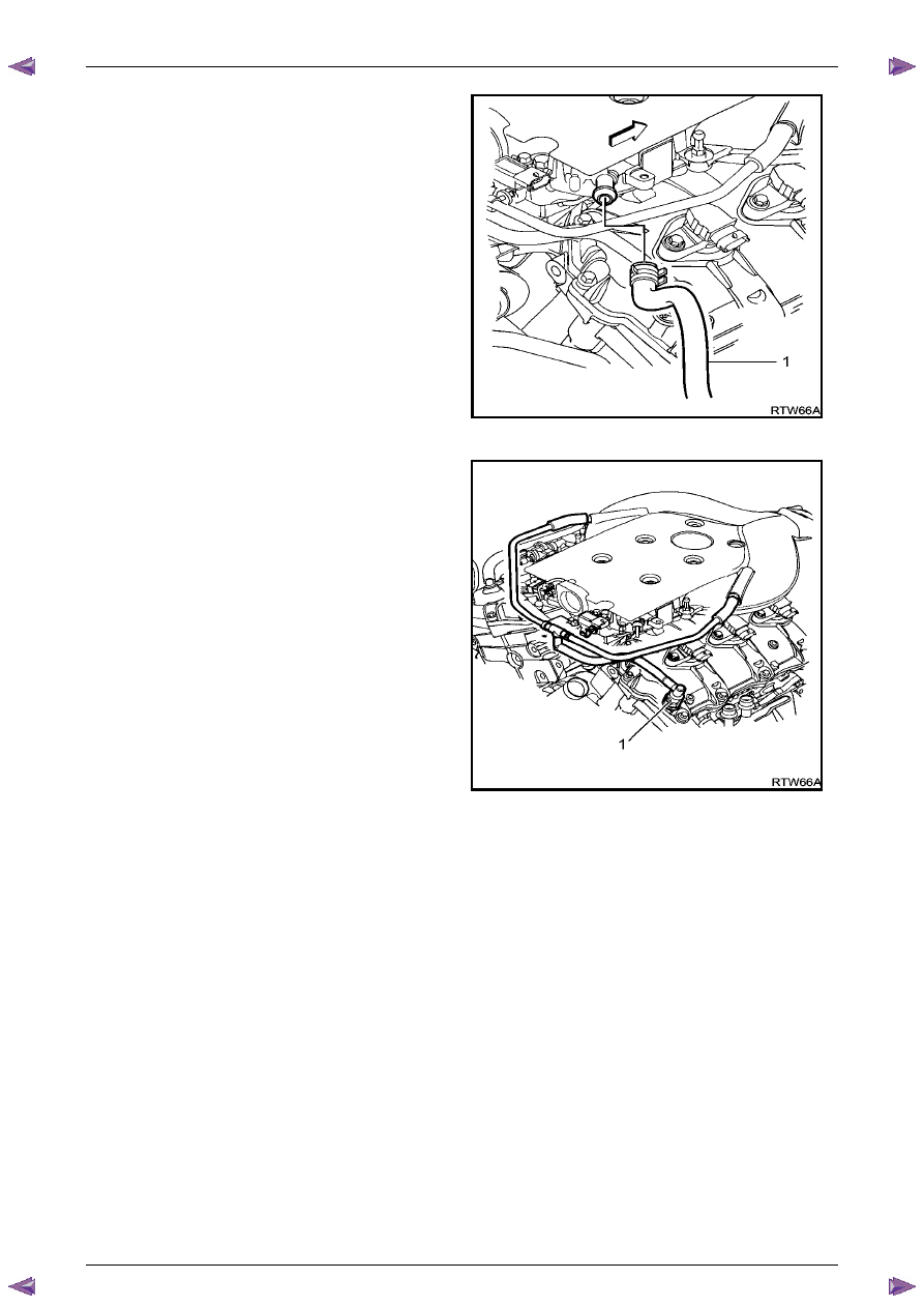
10
Disconnect the vacuum booster hose (1).
Figure 6A1 – 409
11
Disconnect the EVAP purge solenoid connector (1).
Figure 6A1 – 410
Engine Mechanical – V6
Page 6A1–242
Page 6A1–242
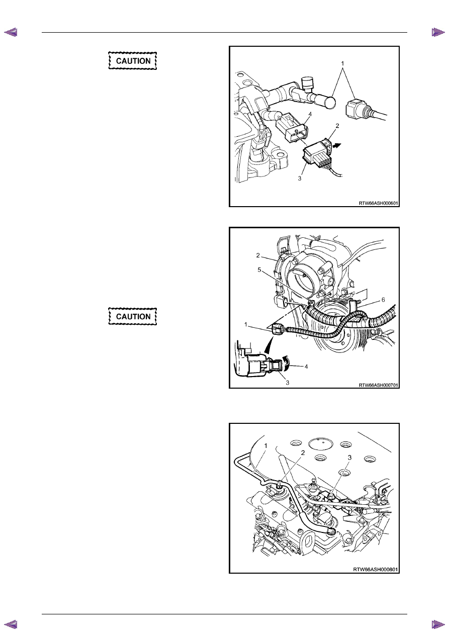
Plug the fuel feed hose after removal to
prevent dirt entering the pipe.
12
Disconnect the fuel pipe connector and injector
harness connector.
13
Disconnect the fuel feed hose from the fuel rail (1),
refer to
Section 6C Fuel system
.
14
Pull out release bar (2) of the fuel injector harness
wiring connector (3).
15
Disconnect the fuel injector harness wiring connector
from the fuel injector wiring harness (4).
Figure 6A1 – 411
16
To disconnect the throttle body connector (1) the
following procedure must be followed.
17
Retract the throttle body wiring connector lock (3)
while pressing the connector latch in the direction of
the arrow (4).
18
Disconnect the throttle body wiring connector (1).
19
Release the throttle body connector wiring harness
from its retaining clip (5).
Take care not to break the barbed retainer
pin (6), when removing the harness. Should
the pin be damaged it is vital that a new
harness retainer be fitted.
20
Remove the main wiring harness retainer pin (6) from
the intake manifold by pushing from the front to the
rear using a suitable length of 5mm steel rod or an
allen key.
Figure 6A1 – 412
21
Disconnect the PCV fresh air tube (1) from the upper
intake manifold mounting clip (2) and remove the
fixing bolt (3).
Figure 6A1 – 413
Нет комментариевНе стесняйтесь поделиться с нами вашим ценным мнением.
Текст