Isuzu KB P190. Manual — part 756
Engine Mechanical – V6
Page 6A1–247
Page 6A1–247
44
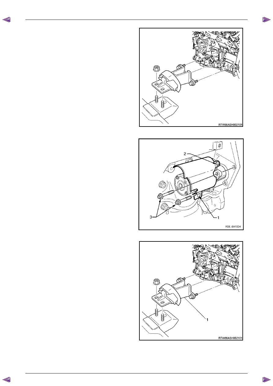
Remove the left-hand side engine mount (1),
(automatic transmission only).
Figure 6A1 – 426
45
Unclip the oil level sensor harness from the heat
shield (1).
a
Remove the heat shield retaining screw (2).
b
Remove the lower starter motor attaching bolt (3).
c
Remove the heat shield.
d
Remove the upper starter motor retaining bolt (3).
46
Remove the starter motor from the engine block and
lower the starter motor as far as possible to gain
access to the wiring harness connections.
47
Remove the starter motor, (automatic transmission
only).
Figure 6A1 – 427
48
Reinstall the left-hand side engine mount (1),
(automatic transmission only).
49
Remove the transmission assembly, refer to
Section 7C1 Automatic – 4L60E – General
Information
.
Figure 6A1 – 428
Engine Mechanical – V6
Page 6A1–248
Page 6A1–248
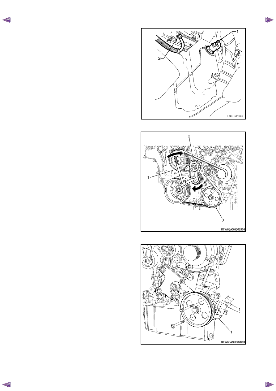
50
Unplug the connector from the oil level sensor (1).
51
Remove the attaching bolt (2) holding the ground
cable to the engine block.
Figure 6A1 – 429
52
Remove the accessory drive belt using a socket
wrench (1), to reduce tension rotate the drive belt
tensioner (2) clockwise, then while holding the
tensioner in the reduced tension position, remove the
accessory drive belt (3).
Figure 6A1 – 430
53
Remove the power steering pump bolts (two places),
remove the pump (1) from the mounting bracket and
disconnect the power steering hoses (two places)
from the pump body.
N O T E
Plug the open ends of the power steering hoses
to prevent the ingress of contaminants.
Figure 6A1 – 431
Engine Mechanical – V6
Page 6A1–249
Page 6A1–249
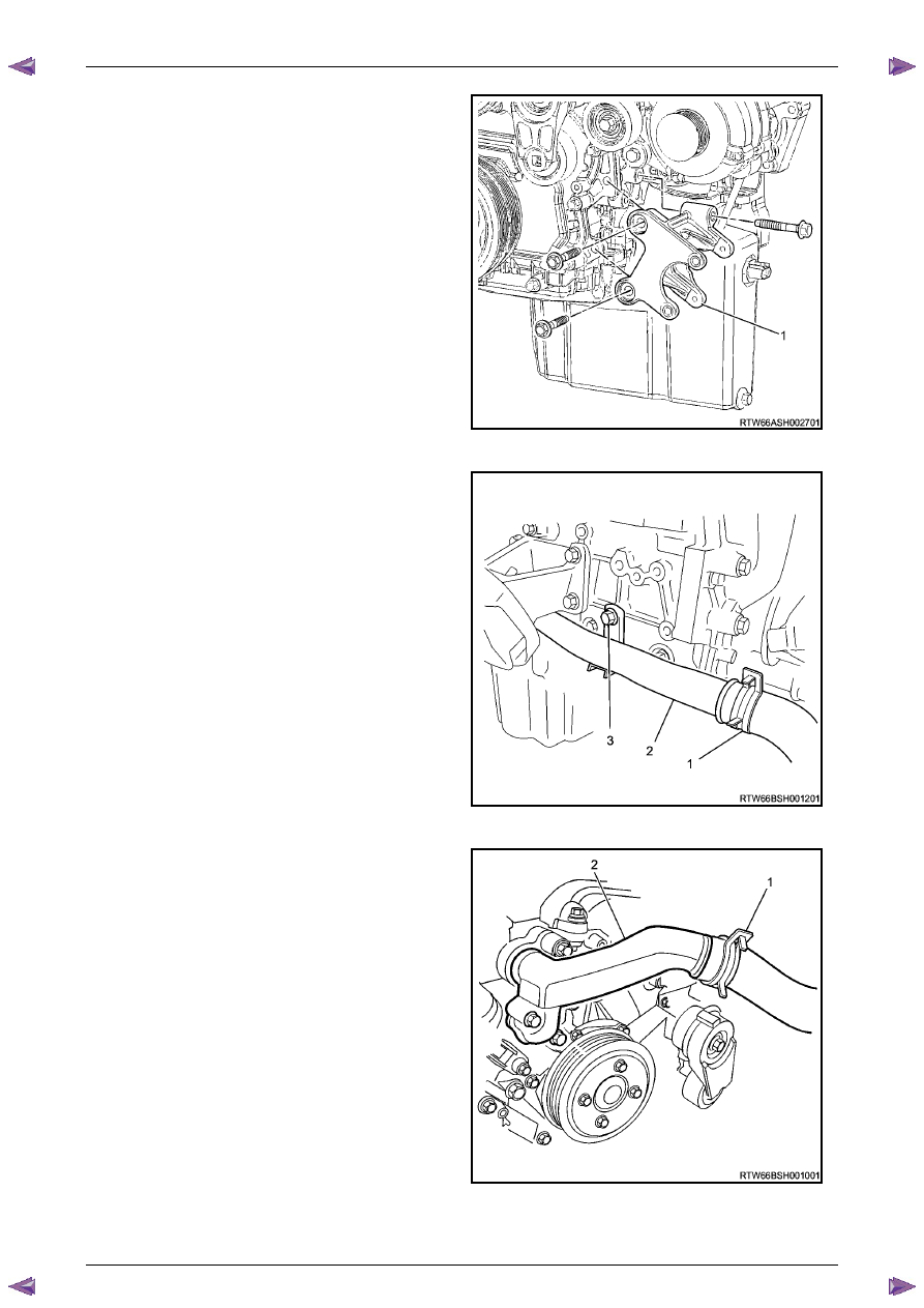
54
Remove the power steering pump bracket mounting
bolts (three places) then remove the pump bracket
(1).
Figure 6A1 – 432
55
Release the lower radiator hose clamp (1) and
remove the lower hose from the coolant pipe (2).
Figure 6A1 – 433
56
Release the upper radiator hose clamp (1) and
remove the upper hose from the coolant pipe (2).
Figure 6A1 – 434
Engine Mechanical – V6
Page 6A1–250
Page 6A1–250
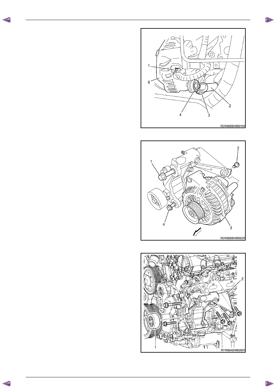
57
Unclip and remove the generator wiring harness
connector (1), Remove battery connection attaching
nut (4), and remove the battery harness cable (2)
from the connection stud.
Figure 6A1 – 435
58
Remove the generator attaching bolts (1, 2, and 4)
three places, then remove the generator (3) from the
mounting bracket.
Figure 6A1 – 436
59
Remove the idler pulley attaching bolt and remove the
idler pulley (1).
60
Remove the generator bracket attaching bolts, five
places, and remove the generator mounting bracket
(2).
Figure 6A1 – 437
Нет комментариевНе стесняйтесь поделиться с нами вашим ценным мнением.
Текст