Isuzu KB P190. Manual — part 249
6C – 32 FUEL SYSTEM
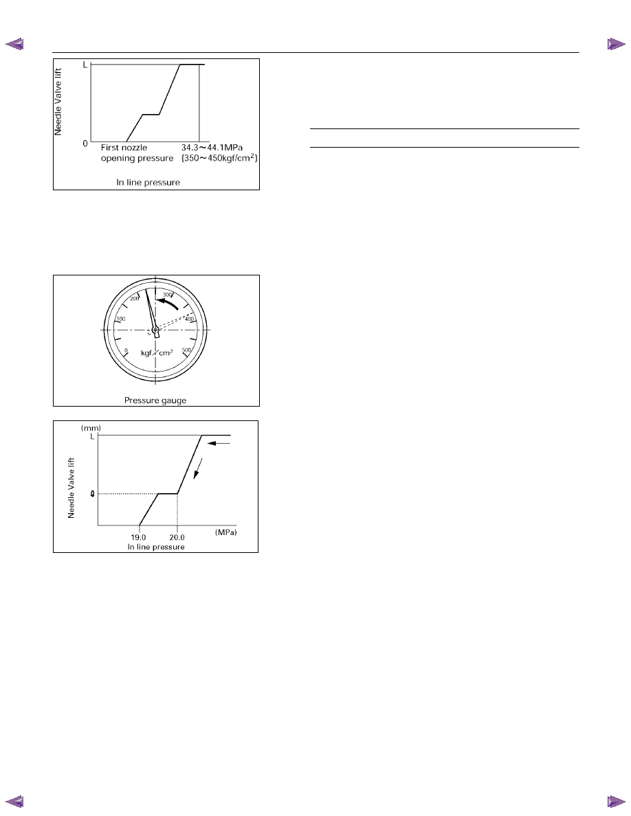
8. Operate the nozzle tester and increase the in-line
pressure to 34.3 - 44.1 MPa (350 - 450 kg/cm
2
) so that
the nozzle’s needle valve moves through its full lift.
Record full lift ‘L’. (Read dial gauge)
Nozzle Full Lift
mm (in)
0.25 ± 0.02 (0.0098 ± 0.00008)
Note:
The above operation is used to determine whether
the nozzle seat is worn and whether the nozzle
assembly is in good condition.
Pre-lift confirmation
1. With the needle valve at full lift, release the nozzle
tester handle.
Note:
The in-line pressure will decrease and needle
valve lift (as indicated on the dial gauge) will also
decrease a little.
040R300008
040MV007.tif
040MV008.tif

FUEL SYSTEM 6C – 33
2. Read the needle valve “pre-lift” point from the dial
gauge indication (once the needle valve has
descended when the second spring has stopped
operating).
Pre-lift measuring point:
Read the dial gauge at first nozzle opening pressure +approx
1 MPa (10 kg/cm
2
).
Pre-lift mm
Pressure Mpa
(psi/ kg/cm
2
)
Lift mm (in)
4JA1T(L)
20.1 (2,858/205)
0.04 (0.0016)
Note:
This point can be found while the pressure is
decreasing.
3. Confirm that pre-lift is as specified.
4. If pre-lift is not as specified, replace the pins, lift piece,
spacer and nozzle assembly as a set with the service
kit.
Service kit
105017-2990 (Bosch AS)
897302-3070 (ISUZU)
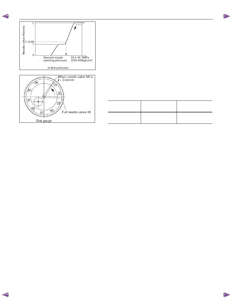
Second nozzle opening pressure confirmation
1. After pre-lift confirmation, operate the nozzle tester to
increase in-line pressure to 34.3 - 44.1 MPa (350 - 450
kg/cm
2
) so that the nozzle’s needle valve moves
through its full lift.
040MV005.tif
040MV031.tif
040MV030.tif
040H100007
6C – 34 FUEL SYSTEM
2. Release the nozzle tester handle so that in-line
pressure decreases.
Note:
The in-line pressure will decrease and needle
valve lift (as indicated on the dial gauge) will also
decrease a little.
3. Then, read the pressure gauge indication (second
nozzle opening pressure) the instant that the dial
gauge indicates the specified needle valve lift (usually
pre-lift + 0.05 mm).
Second Nozzle Opening Pressure
Pressure Mpa
(psi/ kg/cm
2
)
Lift mm (in)
4JA1T(L) 25.5-27.0
(3768-3911/260-275)
0.09 (0.0035)
040MV022.tif
040M100006
FUEL SYSTEM 6C – 35
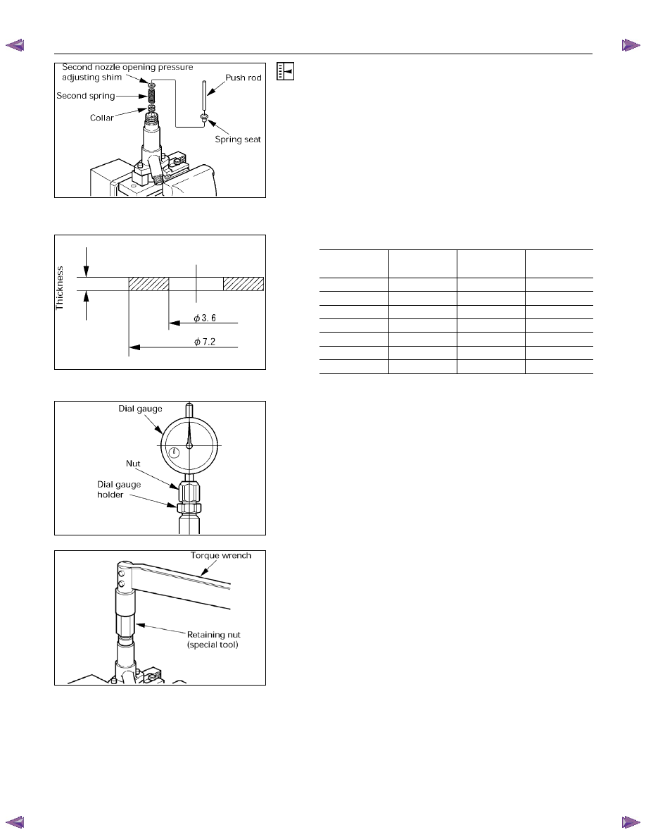
Second nozzle opening pressure adjustment
If the second nozzle opening pressure is not as specified,
disassemble the nozzle from the nozzle holder and
replace the shim until the pressure is as specified.
CAUTION:
•
Because the second opening pressure changes
when the first opening pressure changes, the
second opening pressure must be adjusted when
the first opening pressure changes.
•
Use a micrometer to measure shim thickness.
•
Use some combination of 3 adjusting shims to
adjust the pressure.
•
Second nozzle opening pressure adjusting shims
Part No.
(ISUZU)
Thickness
(mm)
Part No.
(ISUZU)
Thickness
(mm)
897116-0290
0.10 897116-0380 0.53
897116-0320
0.20 897116-0390 0.54
897116-0330
0.30 897116-0400 0.55
897116-0340
0.40 897116-0410 0.56
897116-0350
0.50 897116-0420 0.57
897116-0360
0.51 897116-0430 0.58
897116-0370
0.52 897116-0440 0.59
Final inspection
1. Remove the dial gauge, nut and dial gauge holder.
2. Remove the adjustment retaining nut and gasket.
3. Install the original retaining nut, confirm that the pins
are inserted fully into the nozzle, and then hand-tighten
the retaining nut. Then, tighten the original retaining
nut to the specified torque.
Torque: 7.0 kg·m (50.6 Ib·ft/69 N·m)
040MV017.tif
040LX009.tif
040MV028.tif
040MV014-1.tif
Нет комментариевНе стесняйтесь поделиться с нами вашим ценным мнением.
Текст