Isuzu KB P190. Manual — part 247

6C – 24 FUEL SYSTEM
13. Throttle Position Sensor Harness Connector
(4JA1TC/4JH1TC only)
Reconnect the harness connector to the throttle position
sensor.
14. Power Steering Pump Bracket
15. Fan
16. Vacuum Hose
Connect the vacuum hose to the EGR valve and the
intake throttle.
Euro under
Euro I
Euro II
Euro III
4JA1L without with with Not
used
4JA1TC
Not used
Not used
Not used
With cooler
(EGR cooler)
4JH1TC without
with
with
With
(EGR cooler)
17. Accelerator Control Cable
1) Connect the accelerator cable to the injection pump
(4JA1T) the intake throttle. (4JA1TC/4JH1TC only)
18. Power Steering Pump Assembly
19. Drive Belt
Install the drive belt and adjust the belt tension.
20. Battery
FUEL SYSTEM 6C – 25
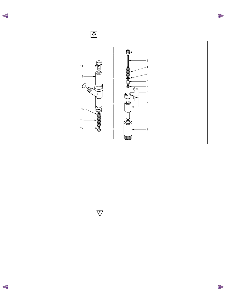
INJECTION NOZZLE (4JA1L)
DISASSEMBLY
RTW76CMF000401
Disassembly Steps
1.
Retaining
nut
2.
Nozzle & pin
3.
Spacer & pin
4.
Lift
Piece
5.
Spring
seat
6.
Push
rod
7.
Shim (Second nozzle opening
pressure adjustment)
8.
Second
spring
9.
Collar
10.
Spring
seat
11.
First
spring
12.
Shim (First nozzle opening
pressure adjustment)
13.
Nozzle holder body
14.
Eye
bolt
Important Operations
Injection nozzle adjustment is possible only on the 4JA1L
engine.
The two-spring nozzle holder has been developed to
reduce NOx (Nitrogen Oxides) and particulates from direct
injection diesel engine exhaust.
Before disassembly remove carbon deposit from nozzle
and nozzle holder using a wire brush and wash the outside
nozzle holder assembly.
Caution:
Do not touch nozzle holes with the wire brush during
cleaning it.
Disassemble the nozzle holder assembly to numerical
order.
6C – 26 FUEL SYSTEM
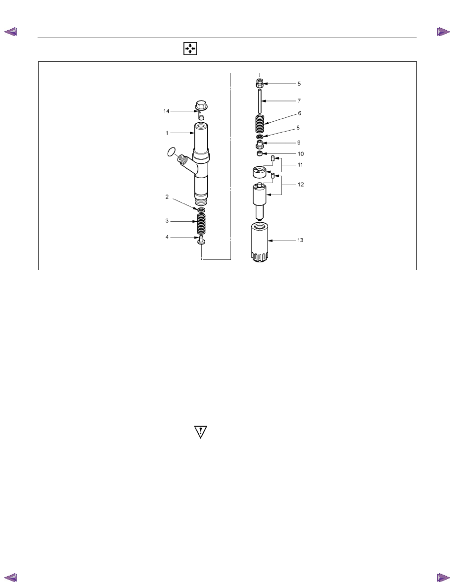
REASSEMBLY
RTW76CMF000501
Reassembly Steps
1.
Nozzle holder body
2.
Shim (First opening pressure
adjustment)
3.
First
spring
4.
Spring
seat
5.
Collar
6.
Second
spring
7.
Push
rod
8.
Shim (Second opening pressure
adjustment)
9.
Spring
seat
10.
Lift
Piece
11.
Spacer & pin
12.
Nozzle & pin
13.
Retaining
nut
14.
Eye
bolt
Important Operations
The nozzle holder is adjusted as the components are
reassembled in the sequence above.
As adjustment of the two-spring nozzle holder is made in
hundredths of a millimeter, clean the parts thoroughly in
light oil to completely remove any dirt or foreign matter.
FUEL SYSTEM 6C – 27
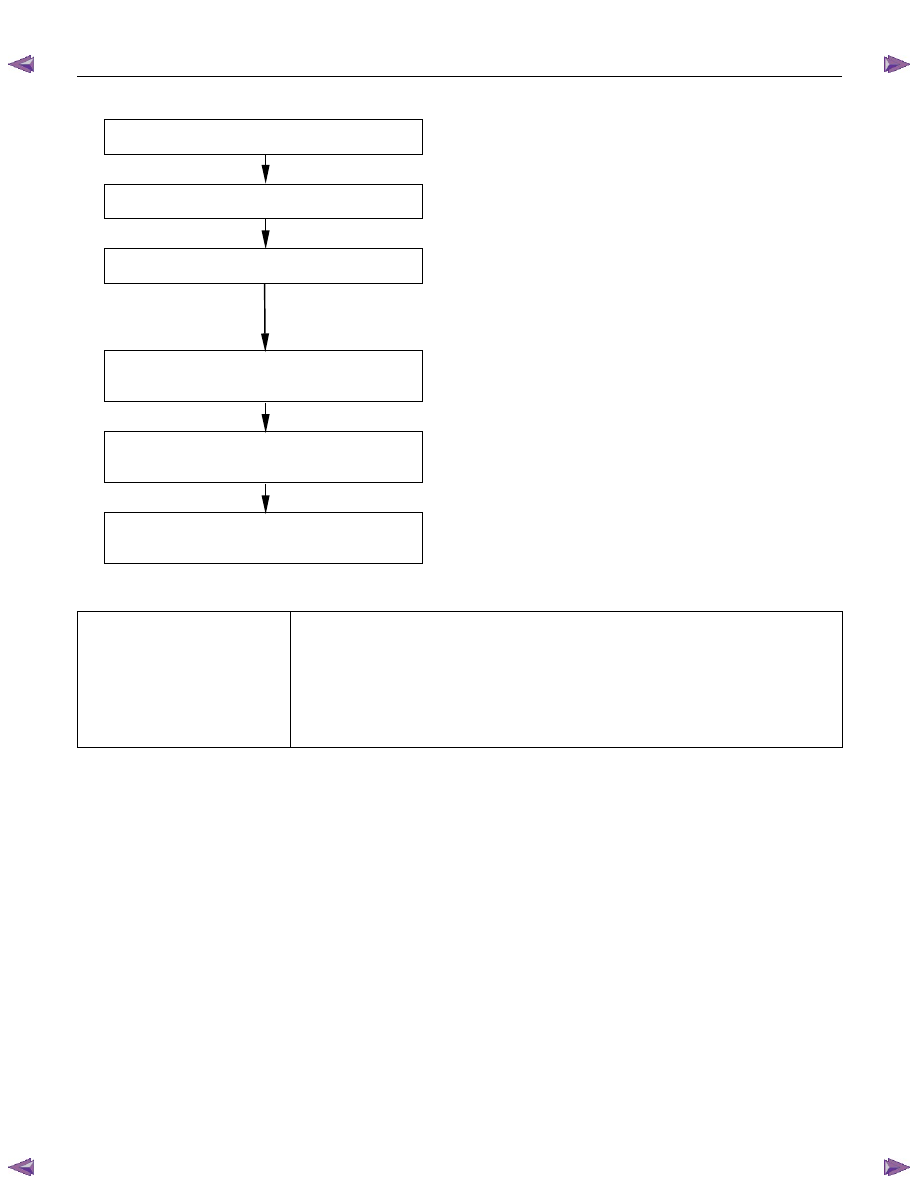
REASSEMBLY AND ADJUSTMENT PROCEDURE
1
First nozzle opening pressure adjustment
Adjust the first nozzle opening pressure using the shim.
2
Full needle valve lift confirmation
Confirm the full needle valve lift in accordance with the
closed method.
3
Pre-lift confirmation
Confirm pre-lift in accordance with the closed method.
CAUTION:
If not as specified, replace the nozzle assembly, lift
piece, pins and spacer using the nozzle service kit.
4
Second nozzle opening pressure
confirmation
Confirm the second nozzle opening pressure in accordance
with the closed method.
5
Second nozzle opening pressure
adjustment
Adjust the second nozzle opening pressure using the shim.
6
Final inspection
Confirm the condition of the fuel spray with the nozzle and
nozzle holder assembled.
First nozzle opening pressure adjustment
Nozzle needle valve full-lift
0.25 mm (0.0098 in)
Nozzle needle valve pre-lift
0.04 mm(0.0016 in) at 20,000 kPa (2901 psi, 204 kg/cm
2
)
Nozzle pressure
4JA1T(L)
1st Stage
19.1 MPa (2759 psi, 194 kg/cm
2
)
2nd Stage
25.5-27.0 MPa (3768-3911 psi, 260-275 kg/cm
2
)
NOTE: Only 4JA1L can perform adjustment of a nozzle.
Нет комментариевНе стесняйтесь поделиться с нами вашим ценным мнением.
Текст