Isuzu KB P190. Manual — part 248
6C – 28 FUEL SYSTEM
Injection Nozzle Adjustment
First nozzle opening pressure adjustment
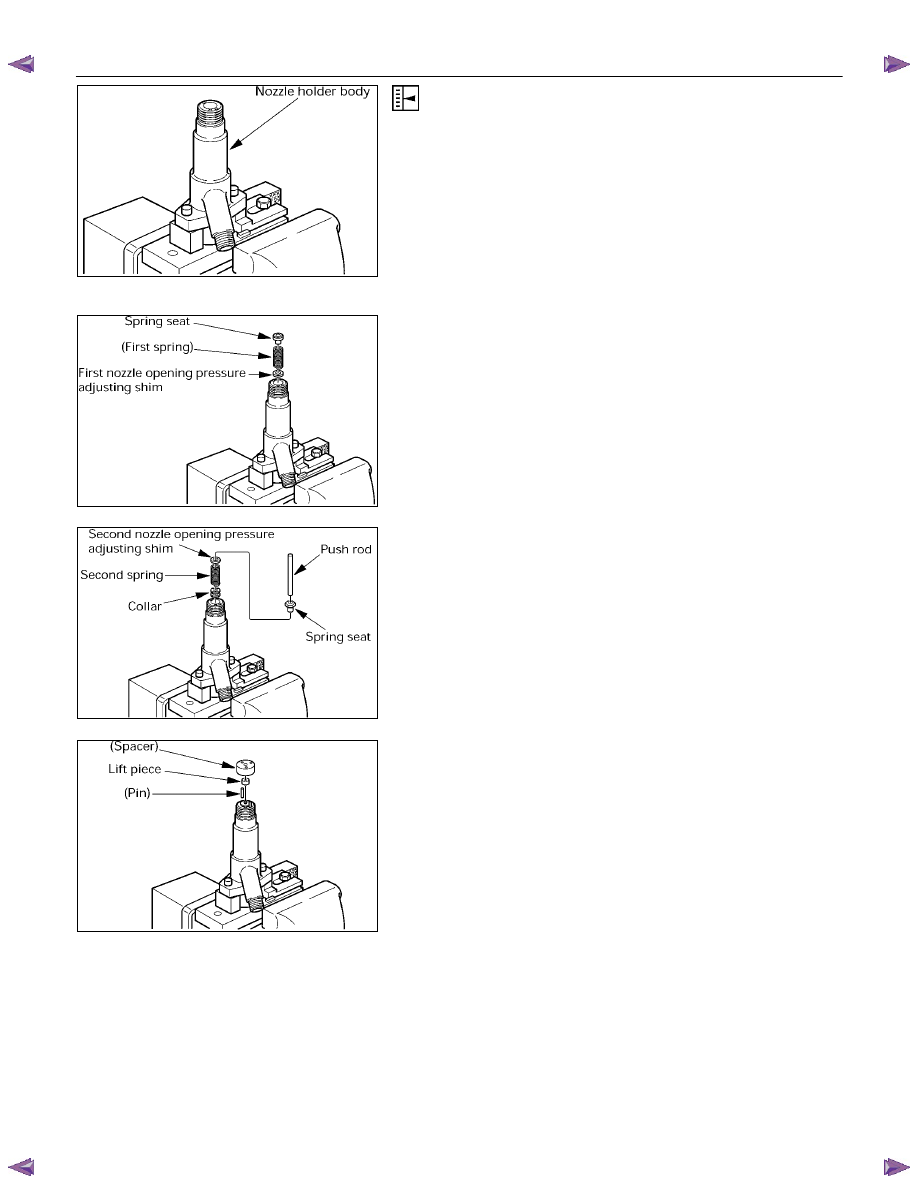
1.Clamp the nozzle holder in a vise.
2. Install the shim, first spring and spring seat in the
nozzle holder.
3. Install the collar, second spring, shim, spring seat and
pushrod in the nozzle holder.
4. Install the pins, lift piece and spacer in the nozzle
holder.
040MV015.tif
040MV016.tif
040MV017.tif
040MV018.tif
FUEL SYSTEM 6C – 29
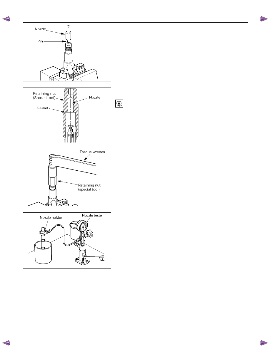
5. Install the pins in the spacer.
6. Install the nozzle on the spacer.
7. Hand-tighten the adjustment retaining nut together
with the gasket to the nozzle holder.
Retaining nut:
157892-3200 (Bosch AS)
Gasket:
157892-5100 (Bosch AS)
(Bosch AS = Bosch Automotive Systems Corporation)
8. Tighten the adjustment retaining nut to the specified
torque.
Torque: 5.1 kg·m (36.9 Ib·ft/50 N·m)
9. Set the nozzle holder to the nozzle tester.
10. Operate the nozzle tester and measure the first nozzle
opening pressure.
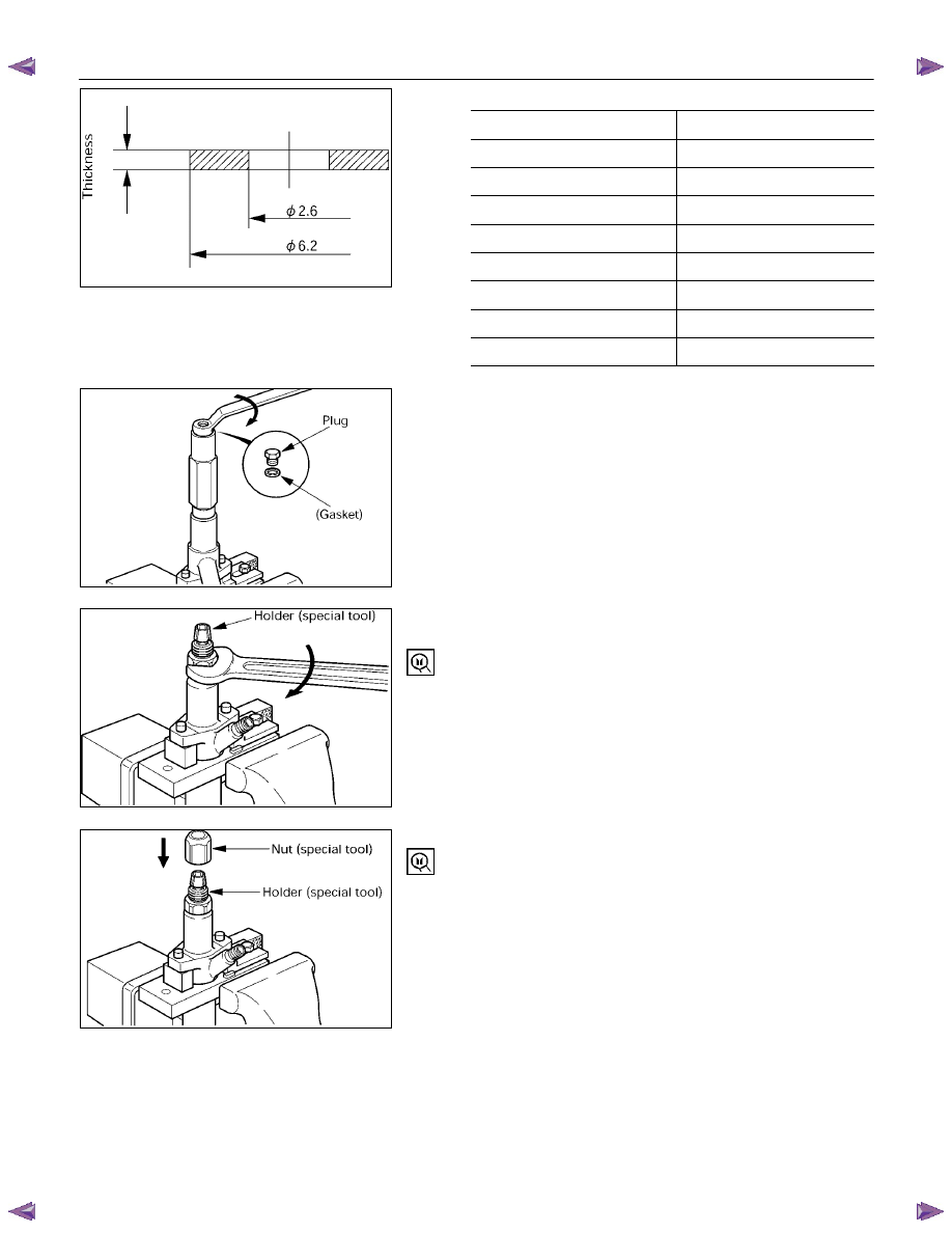
11. If the first nozzle opening pressure is not as specified,
disassemble the nozzle holder and replace the shim
until the pressure is as specified.
CAUTION:
•
Use a micrometer to measure shim thickness.
040MV019.tif
040MV010.tif
040MV014-1.tif
040MV030.tif
6C – 30 FUEL SYSTEM
•
First nozzle opening pressure adjusting shims
Parts No. (ISUZU)
Thickness (mm)
115349-0420 0.40
115349-0430 0.50
115349-0440 0.52
115349-0450 0.54
115349-0460 0.56
115349-0470 0.58
115349-0480 0.60
115349-0490 0.70
Full needle valve lift confirmation
1. Install the gasket and plug on the adjustment retaining
nut.
Gasket:
026508-1140 (Bosch AS)
8-9422-7602-0 (ISUZU)
Plug:
157892-1600 (Bosch AS)
2. Position the nozzle holder with the nozzle facing down
and install the dial gauge holder on the nozzle holder.
Dial gauge holder: 157892-5000 (Bosch AS)
3. Install the nut on the dial gauge holder.
Nut: 157892-1000 (Bosch AS)
040LX010.tif
040MV013.tif
040MV012.tif
040MV011.tif
FUEL SYSTEM 6C – 31
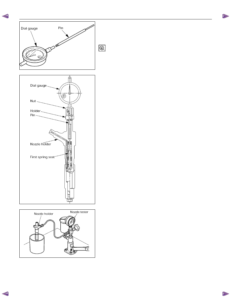
4. Install the pin to the dial gauge.
Note:
The lengths of the pins do not include the
threaded portions.
Pin (L=100 mm): 157892-5200 (Bosch AS)
Dial gauge:
157954-3800 (Bosch AS)
185317-0150 (ISUZU)
5. Secure the dial gauge to the nozzle holder using the
nut so that the pin contacts the tip of the first spring
seat.
CAUTION:
•
Secure the dial gauge so that a stroke of 2 mm can
be measured.
•
Do not over-tighten the nut as the dial gauge shaft
may jam. (Confirm from the dial gauge that the
shaft moves smoothly.)
6. Set the nozzle holder to the nozzle tester and put
needle to zero on the dial gauge.
7. Operate the nozzle tester to bleed any air from inside
the retaining nut and to confirm that no fuel leaks.
040MV029.tif
040MV009.tif
040MV030.tif
Нет комментариевНе стесняйтесь поделиться с нами вашим ценным мнением.
Текст