Isuzu KB P190. Manual — part 757
Engine Mechanical – V6
Page 6A1–251
Page 6A1–251
61
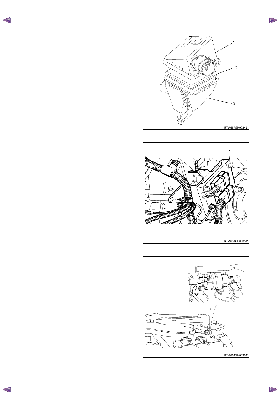
Remove the air cleaner cover assembly including the
MAF sensor assembly (1).
62
Remove the air cleaner filter (2) from the air cleaner
body assembly (3).
Figure 6A1 – 438
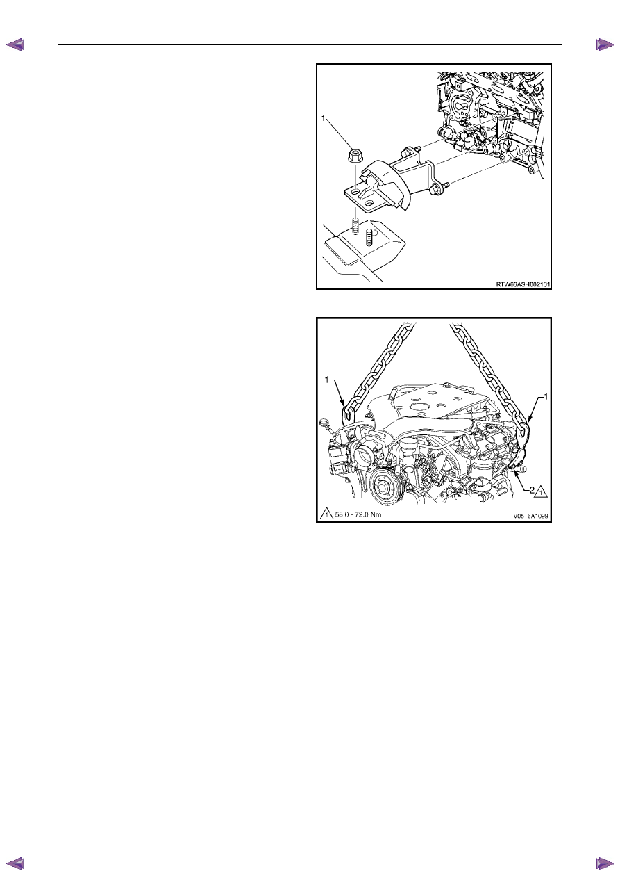
63
Disconnect the ECM connectors (1).
Figure 6A1 – 439
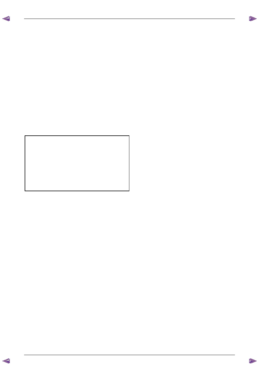
64
Disconnect the canister hose (1).
Figure 6A1 – 440
Engine Mechanical – V6
Page 6A1–252
Page 6A1–252
65
Remove the engine mount attaching nuts (1), (two
places) on the chassis side of the left-hand and right-
hand engine mounts.
Figure 6A1 – 441
66
Slowly raise the engine using the engine hoist
continue to lift and manoeuvre the engine assembly
clear of the engine compartment.
Figure 6A1 – 442
Disassemble
1
Remove the wiring harness connectors and ground connections from the engine and transmission assembly and
carefully set the wiring harness to one side, refer to
Section 8A Electrical Body & Chassis
.
2
Remove the engine control module (ECM) and mounting bracket, refer to
Section 6C1-3 Engine Management – V6
– Service Operations
.
3
Mount the engine assembly on a suitable engine stand.
5
Drain the engine oil into a suitable, clean container.
6
Remove the following components:
a
Oil filter adaptor, refer to
3.3 Oil Filter Adaptor
.
b
Engine coolant inlet pipe, refer to
Section 6B1 Engine Cooling – V6
.
c
Heater pipe assembly, refer to
Section 6B1 Engine Cooling – V6
.
d
Thermostat assembly, refer to
Section 6B1 Engine Cooling – V6
.
e
Exhaust manifold assemblies, refer to
3.11 Exhaust Manifold Assembly
.
f
Engine coolant outlet pipe, refer to
Section 6B1 Engine Cooling – V6
.
g
Crankshaft position sensor, refer to
Section 6C1-3 Engine Management – V6 – Service Operations
.
h
Knock sensors, refer to
Section 6C1-3 Engine Management – V6 – Service Operations
.
i
Engine mounts and brackets, refer to
3.23 Engine Mounts and Brackets
.
j
Flexplate assemblies, refer to
4.3 Flexplate Assembly
.
Engine Mechanical – V6
Page 6A1–253
Page 6A1–253
k
Timing chains, tensioners, shoes, guides & sprockets, refer to
3.16 Timing Chains, Tensioners, Shoes and
Guides
.
l
Cylinder head assemblies, refer to
3.22 Cylinder Head Assembly
.
m
Oil pan assembly, refer to
4.2 Oil Pan and Oil Pump Suction Pipe Assembly
.
n
Piston and connecting rod assemblies, refer to
4.5 Pistons, Pins, Rings, Connecting Rods and Big-end
Bearings
.
o
Crankshaft assembly, refer to
4.6 Crankshaft and Main Bearings
.
p
Piston oil nozzles, refer
4.5 Pistons, Pins, Rings, Connecting Rods and Big-end Bearings
.
Reassemble
Reassembly of the engine assembly is the reverse of the disassembly procedure.
Reinstall
Reinstallation of the engine assembly is the reverse to the removal procedure, noting the following:
N O T E
Refer to
6 Torque Wrench Specifications
for the
correct torque specifications.
1
Tighten the fasteners to the correct torque specification.
Engine ground connector bolt
torque specification . . . . . . . . . . . 10.0 Nm
Power steering high pressure line
attaching bolt torque specification. . . .8.0 – 12.0 Nm
Power steering high pressure line
flare nut torque specification . . . . ...25.0 – 35.0 Nm
Engine mount to frame attaching bolt
torque specification . . . . . . . . .44.0 – 60.0 Nm
Knock Sensor Attaching Nut
torque specification . . . . . . . . . . . 23.0 Nm
2
Use only the specified engine lubricant type and quantity. It is recommended that a fluorescent oil dye, such as that
contained in J 28481-B, be added to assist in any future oil leak diagnosis.
3
Fill the cooling system with the correct quantity and grade of coolant, refer to
Section 6B1 Engine Cooling – V6
.
4
Check transmission fluid level, replenishing as required, using the specified lubricant for the transmission fitted,
refer to
Section 7C1 Automatic – 4L60E – General Information
.
5
Disable the ignition system, refer to
Section 6C1-3 Engine Management – V6 – Service Operations
.
6
Crank the engine several times. Listen for any unusual noises or evidence that parts are binding.
7
Enable the ignition system. Start the engine and listen for any unusual noises.
8
Check the vehicle oil pressure gauge or warning indicator and confirm the engine has acceptable oil pressure. If
required, install an oil pressure gauge and measure the engine oil pressure, refer to
2.19 Engine Oil Pressure
Diagnosis
.
9
Run the engine at about 1,000 r.p.m. until the engine has reached normal operating temperature.
10
Listen for any unusual noises.
11
Check for oil, fuel, coolant and exhaust leaks while the engine is running, correcting as required.
12
Perform a final inspection for correct engine oil and coolant levels.
Engine Mechanical – V6
Page 6A1–254
Page 6A1–254
4.2
Oil Pan and Oil Pump Suction Pipe
Assembly
Remove
1
Remove the engine assembly from the vehicle, refer to
4.1 Engine
.
2
Separate the engine and transmission assemblies, refer to
Section 7C1 Automatic – 4L60E – General Information
.
3
Mount the engine assembly on a suitable engine stand.
4
Remove the engine front cover, refer to
3.15 Front Cover Assembly
.
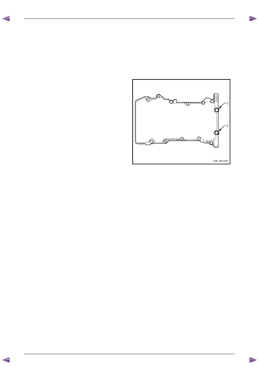
5
Remove the two long bolts (1) attaching the rear of
the oil pan to the crankshaft rear oil seal housing.
6
Remove the remaining eleven bolts attaching the oil
pan to the cylinder block.
7
Using the shear points located at the edge of the oil
pan shear the RTV sealant.
8
Remove the oil pan from the cylinder block.
Figure 6A1 – 443
Нет комментариевНе стесняйтесь поделиться с нами вашим ценным мнением.
Текст