Isuzu KB P190. Manual — part 217
ENGINE MECHANICAL 6A – 63
Measuring Method-II
1. Measure the valve stem outside diameter.
Refer to the Item "Valve Stem Outside Diameter".
2. Use a caliper calibrator or a telescoping gauge to measure
the valve guide inside diameter.
Valve Guide Replacement
Valve Guide Removal
Use a hammer and the valve guide replacer to drive out the
valve guide from the cylinder head lower face.
Valve Guide Replacer: 9-8523-1212-0
Valve Guide Installation
1. Apply engine oil to the valve guide outer circumference.
2. Attach the valve guide installer to the valve guide.
3. Use a hammer to drive the valve guide into position from
the cylinder head upper face.
Valve Guide Replacer: 9-8523-1212-0
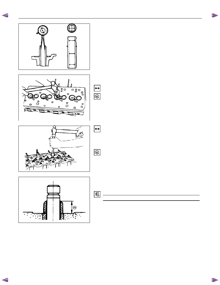
4. Measure the height of the valve guide upper end from the
upper face of the cylinder head.
Valve Guide Upper End Height (H) (Reference)
mm (in)
12.8-13.2 (0.50-0.52)
NOTE:
If the valve guide has been removed, both the valve
and the valve guide must be replaced as a set.
011LX029
011RY00024
011RY000025
011RY00023
6A – 64 ENGINE MECHANICAL
Valve Stem Outside Diameter
Measure the valve stem diameter at three points.
If the measured value is less than the specified limit, the valve
and the valve guide must be replaced as a set.
Valve Stem Outside Diameter
mm (in)
Standard
Limit
Intake Valve
7.946 - 7.961
(0.3128 - 0.3134)
7.880
(0.3102)
Exhaust Valve
7.921 - 7.936
(0.3119 - 0.3124)
7.850
(0.3090)
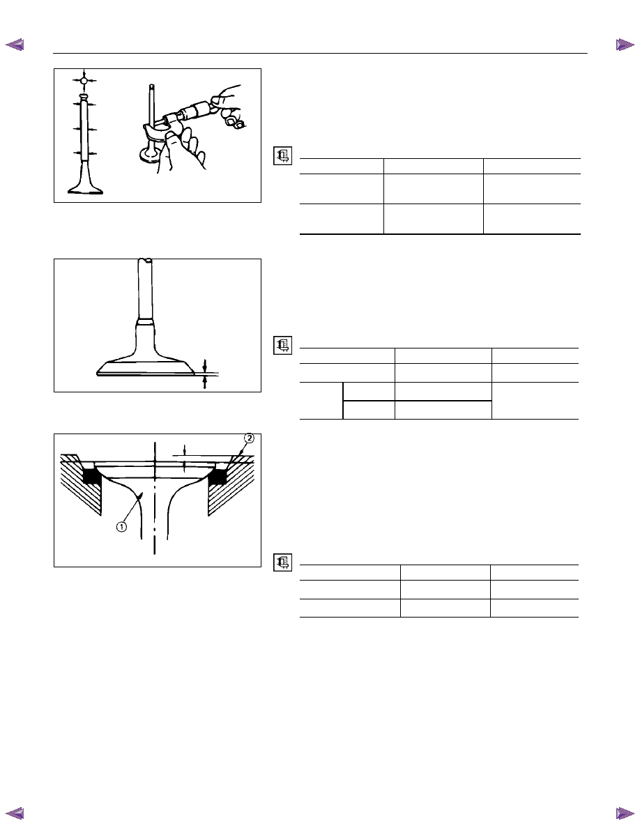
Valve Thickness
Measure the valve thickness.
If the measured value is less than the specified limit, the valve
and the valve guide must be replaced as a set.
Intake and Exhaust Valve Thickness
mm (in)
Standard
Limit
4JA1T (L)
1.8 (0.07)
1.5 (0.06)
Inlet 1.34
(0.054)
4JA1TC,
4JH1TC
Exhaust 1.36
(0.055)
1.1 (0.045)
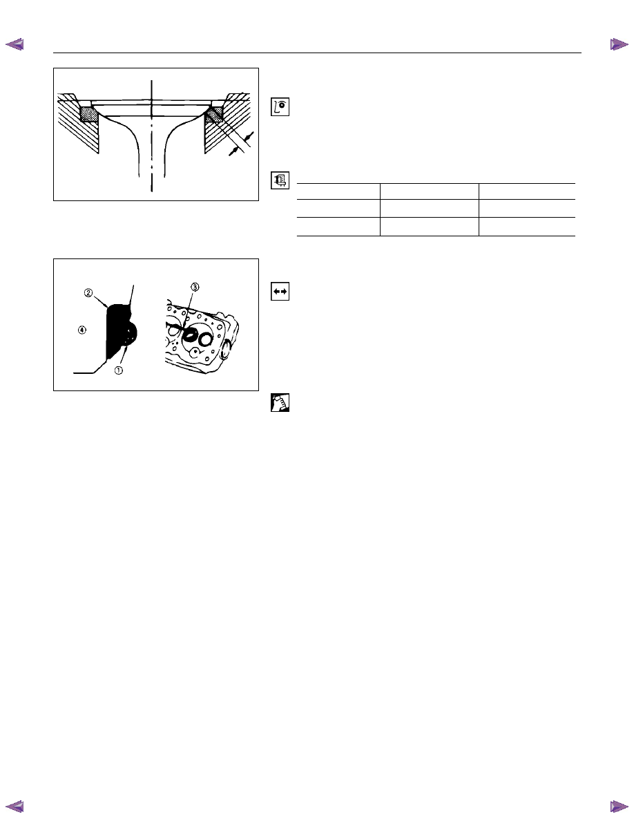
Valve Depression
1. Install the valve (1) to the cylinder head (2).
2. Use a depth gauge or a straight edge with steel rule to
measure the valve depression from the cylinder head lower
surface.
If the measured value exceeds the specified limit, the valve
seat insert must be replaced.
Valve Depression
mm (in)
Standard
Limit
4JA1T(L)
0.72 (0.029)
1.28 (0.050)
4JA1TC, 4JH1TC
1.17 (0.048)
1.67 (0.068)
011LX027
014RY00020
014RY00021
ENGINE MECHANICAL 6A – 65
Valve Contact Width
1. Check the valve contact faces for roughness and
unevenness. Make smooth the valve contact surfaces.
2. Measure the valve contact width.
If the measured value exceeds the specified limit, the valve
seat insert must be replaced.
Valve Contact Width
mm (in)
Standard
Limit
Intake
1.7 (0.067)
2.2 (0.087)
Exhaust
2.0 (0.079)
2.5 (0.078)
Valve Seat Insert Replacement
Valve Seat Insert Removal
1. Arc weld the entire inside circumference (1) of the valve
seat insert (2).
2. Allow the valve seat insert to cool for a few minutes.
This will invite contraction and make removal of the valve
seat insert easier.
3. Use a screwdriver (3) to pry the valve seat insert free.
Take care not to damage the cylinder head (4).
4. Carefully remove carbon and other foreign material from
the cylinder head insert bore.
014RY00027
011LX039

6A – 66 ENGINE MECHANICAL
Valve Seat Insert Installation
1. Carefully place the attachment (1) (having a smaller
outside diameter than the valve seat insert) on the valve
seat insert (2).
NOTE:
The smooth side of the attachment must contact the
valve seat insert.
2. Use a bench press (3) to gradually apply pressure to the
attachment and press the valve seat insert into place.
NOTE:
Do not apply an excessive amount of pressure with
the bench press. Damage to the valve seat insert will
result.
Valve Seat Insert Correction
1. Remove the carbon from the valve seat insert surface.
2. Use a valve cutter (15
°
, 45
°
, and 75
°
blades) to minimize
scratches and other rough areas. This will bring the
contact width back to the standard value.
Remove only the scratches and rough areas. Do not cut
away too much. Take care not to cut away unblemished
areas of the valve seat surface.
Valve Seat Angle
Degree
45
NOTE:
Use an adjustable valve cutter pilot.
Do not allow the valve cutter pilot to wobble inside the
valve guide.
3. Apply abrasive compound to the valve seat insert surface.
4. Insert the valve into the valve guide.
5. Turn the valve while tapping it to fit the valve seat insert.
6. Check that the valve contact width is correct.
7. Check that the valve seat insert surface is in contact with
the entire circumference of the valve.
011LX063
014RY00026
011LX037
011LX038
Нет комментариевНе стесняйтесь поделиться с нами вашим ценным мнением.
Текст