Isuzu KB P190. Manual — part 759
Engine Mechanical – V6
Page 6A1–259
Page 6A1–259
4.3 Flexplate
Assembly
Remove
1
Remove the transmission, refer to
Section 7C4 Automatic Transmission – 4L60E – On-vehicle Servicing
.
2
Remove the starter motor, refer to
Section 6D1-2 Starting System – V6
.
3
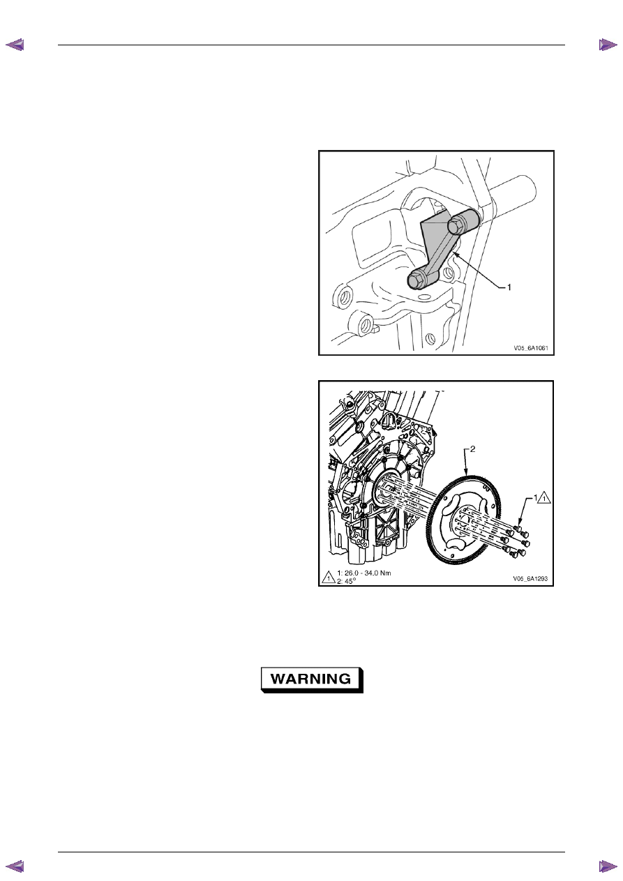
Install the flexplate holding tool, Tool No. EN-46106
(1) into the starter motor mounting location.
Figure 6A1 – 452
4
Loosen the eight flexplate attaching bolts (1).
5
Remove the flexplate holding tool.
6
Using a suitable permanent marker or paint pen, mark
the flexplate assembly (2) to crankshaft relationship.
7
Remove the eight flexplate attaching bolts and
discard.
8
Remove the flexplate assembly.
Figure 6A1 – 453
Clean
1
Clean the flexplate assembly in a suitable solvent.
Safety glasses must be worn when using
compressed air.
2
Dry the flexplate assembly with compressed air.

Engine Mechanical – V6
Page 6A1–260
Page 6A1–260
Inspect
1
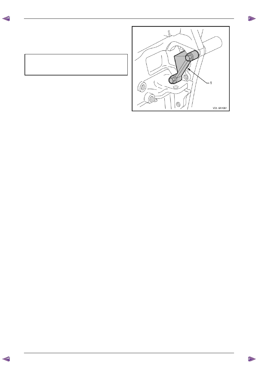
Inspect the flexplate assembly for the following
conditions:
•
Stress cracks around the flexplate to torque
converter mounting bolt hole locations (1).
•
Stress cracks around the flexplate to crankshaft
mounting bolt hole locations (2 and 4).
•
Cracks at welded areas that retain the ring gear
onto the flexplate (3).
•
Damaged or missing ring gear teeth (5).
2
Replace the flexplate assembly as required.
N O T E
The flexplate ring gear is not serviced
separately and cannot be repaired. If found to
be faulty or damaged, the flexplate assembly
must be replaced.
CAUTION
Do not repair the welded areas that retain
the ring gear to the flexplate. The flexplate
must be replaced.
Figure 6A1 – 454
Reinstall
N O T E
The bolt holes are unevenly spaced to enable
flexplate fitment in the one position only.
1
Place the flexplate assembly (2) in position on the
crankshaft.
2
Install new flexplate attaching bolts (1) and hand
tighten.
Figure 6A1 – 455
Engine Mechanical – V6
Page 6A1–261
Page 6A1–261
3
Install the flexplate holding tool, Tool No. EN-46106
(1) into the starter motor mounting location.
4
Tighten the eight flexplate attaching bolts to the
correct torque specification.
Flexplate attaching bolt
torque specification:
Stage
1 . . . ..26.0 – 34.0 Nm
Stage
2 . . . . . . . . .45°
5
Remove the flexplate holding tool.
6
Install the starter motor, refer to
Section 6D1-2
Starting System – V6
.
7
Install the transmission, refer to
Section 7E4
Automatic Transmission – 4L60E – On-vehicle
Servicing
.
Figure 6A1 – 456

Engine Mechanical – V6
Page 6A1–262
Page 6A1–262
4.4
Crankshaft Rear Seal and Plate
Assembly
Remove
1
Remove the engine assembly, refer to
4.1 Engine
.
2
Remove the flexplate assembly, refer to
4.3 Flexplate Assembly
.
3
Remove the engine oil pan assembly, refer to
4.2 Oil Pan and Oil Pump Suction Pipe Assembly
.
4
Remove the five bolts (1) attaching the crankshaft
rear seal housing to the rear of the cylinder block (2).
Figure 6A1 – 457
5
Shear the RTV sealant using the prise points located
at the edge of the crankshaft rear oil seal housing,
Figure 6A1 – 458
Нет комментариевНе стесняйтесь поделиться с нами вашим ценным мнением.
Текст