Isuzu KB P190. Manual — part 888
Engine Management – V6 – Service Operations
Page 6C1-3–28
2
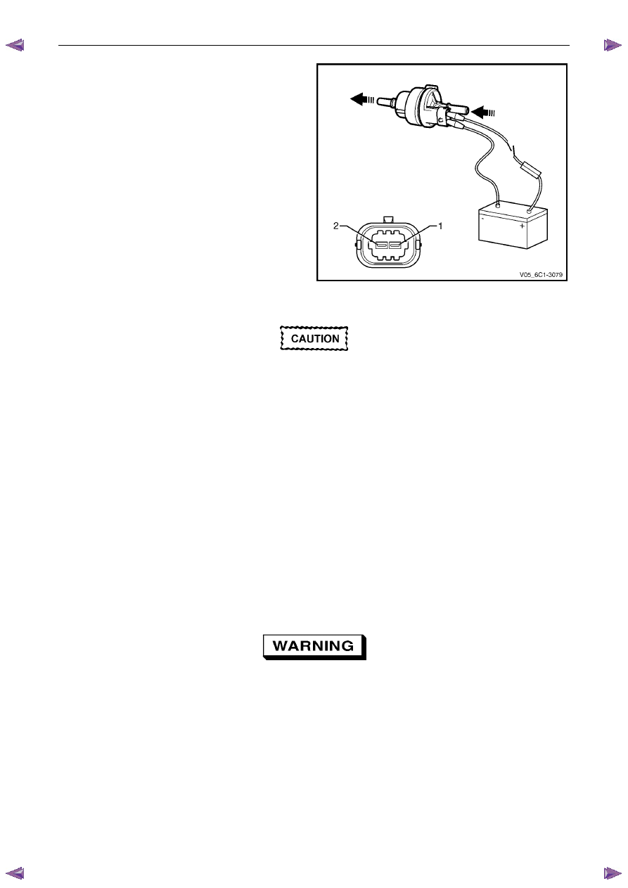
Using connector test adaptor kit J 35616-A, connect a
12 V battery, an on / off switch and a 3 A fused wire to
the EVAP canister purge valve terminals as follows:
•
Positive lead to terminal 1.
•
Negative lead to terminal 2.
Figure 6C1-3 – 31
Do not apply 12 V to the EVAP canister purge
valve continuously for more than three
seconds as the EVAP canister purge valve
will be damaged.
3
Turn the switch on, and listen for an audible click as the EVAP canister purge valve operates. Whilst the switch is in
the on position, blow air through the inlet port.
4
If no air passes through the EVAP canister purge valve, check the valve inlet and outlet ports for any obstructions
and rectify if necessary. If there are no obstructions, replace the valve.
Reinstall
Reinstallation of the evaporative emission canister purge valve is the reverse of the removal procedure, noting the
following:
1
Connect the purge valve hose quick connect fittings, refer to 2.11 Evaporative Emission (EVAP) Canister Purge
Valve Quick Connect Fittings.
2
Road test the vehicle and check for correct operation, taking particular note that no air leaks are evident.
2.13 Fuel Rail Assembly
A depressurised fuel system contains
residual fuel that can be spilled during service
operations, refer to 6C Fuel System – V6 for
further information on handling fuel.
Remove
1
Depressurise the fuel system, refer to 6C Fuel System - V6.
2
Turn the ignition switch off.
Engine Management – V6 – Service Operations
Page 6C1-3–29
N O T E
After removing the upper intake manifold, plug
the lower manifold opening to prevent dirt and
other contaminants from entering.
3
Remove the upper intake manifold assembly, refer to 6A1 Engine Mechanical – V6.
4
Disconnect the fuel feed hose from the fuel rail, refer to 6C Fuel System - V6. Plug the fuel line openings to prevent
dirt and other contaminants from entering.
5
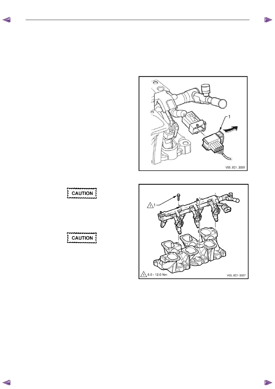
Slide the engine wiring harness connector retaining
latch (1) in the direction of the arrow to disconnect the
connector from the fuel injector harness.
Figure 6C1-3 – 32
Clean around the area where the fuel
injectors enter the lower intake manifold.
6
Remove the bolt (1), three places, attaching the fuel
rail to the lower intake manifold.
Care must be taken when removing the fuel
rail and injector assembly to prevent damage
to the injector spray tips and injector harness
connector terminals.
Support the fuel rail and injector assembly
after removal.
7
Remove the fuel rail and injector assembly.
8
Plug all fuel line and manifold openings after removal
to prevent dirt and other contaminants from entering.
Figure 6C1-3 – 33
Engine Management – V6 – Service Operations
Page 6C1-3–30
Disassemble
Fuel Injector
Remove
For each fuel injector:
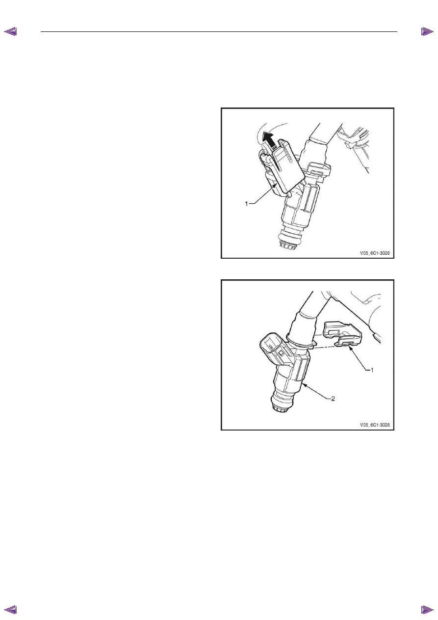
1
Slide the fuel injector wiring connector locking tab (1)
upwards in the direction of the arrow.
2
Disconnect the connector from the fuel injector.
Figure 6C1-3 – 34
3
Using a flat blade screwdriver, remove the fuel injector
retaining clip (1) from the fuel injector (2). Discard the
retaining clip.
Figure 6C1-3 – 35

Engine Management – V6 – Service Operations
Page 6C1-3–31
4
Remove the fuel injector (1) from the fuel rail.
5
Remove and discard the fuel injector seals (2).
6
As required, repeat for the remaining injectors and test
each fuel injector, refer to the Test in this Section.
Figure 6C1-3 – 36
Test
To prevent component damage use connector
test adaptor kit J 35616-A.
1
Connect a digital ohmmeter using connector test
adaptor kit J 35616-A to the fuel injector.
2
Measure the resistance across terminals A and B.
3
Compare the reading against the specification.
Fuel injector resistance @ 20°C . . . ... 11.4 – 12.6
Ω
4
If the resistance is not within specifications, replace
the fuel injector.
Figure 6C1-3 – 37
Reinstall
Reinstallation of the fuel injector is the reverse of the removal procedure, noting the following:
1
Install new fuel injector seals and lubricate with clean engine oil.
2
Install a new fuel injector retaining clip, refer to Figure 6C1-3 – 35.
Нет комментариевНе стесняйтесь поделиться с нами вашим ценным мнением.
Текст