Isuzu KB P190. Manual — part 889
Engine Management – V6 – Service Operations
Page 6C1-3–32
Fuel Injector Wiring Harness Assembly
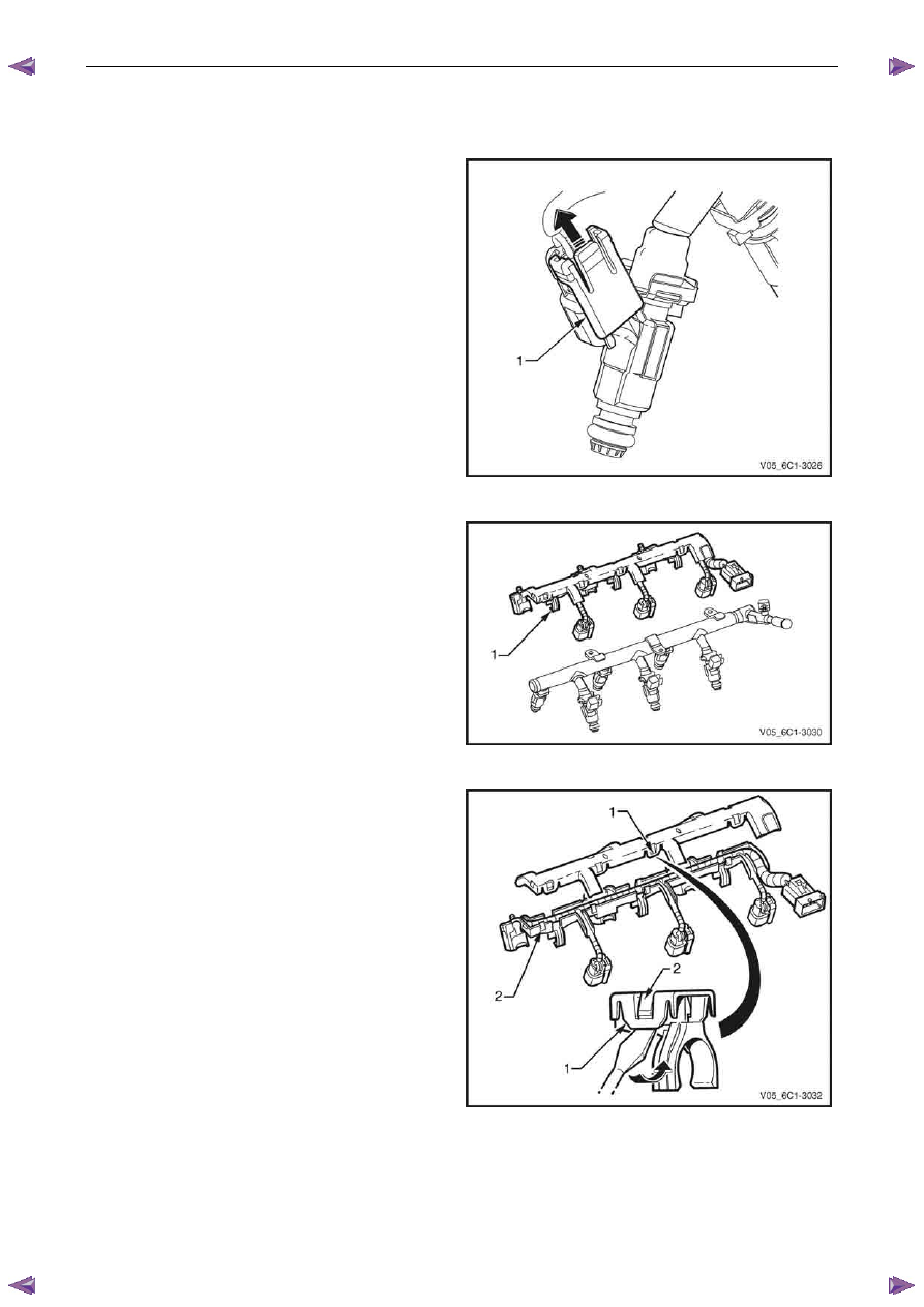
Remove
1
For each fuel injector wiring harness connector, slide
the locking tab (1) upwards in the direction of the
arrow and disconnect the connector from the fuel
injector.
Figure 6C1-3 – 38
2
Unclip the fuel injector harness assembly (1), three
places, from the fuel rail.
Figure 6C1-3 – 39
3
Using a flat blade screwdriver, prise the fuel injector
harness upper tray retainer (1), eight places, from the
lower tray locking tang (2).
4
Remove the fuel injector harness from the lower tray.
Figure 6C1-3 – 40
Engine Management – V6 – Service Operations
Page 6C1-3–33
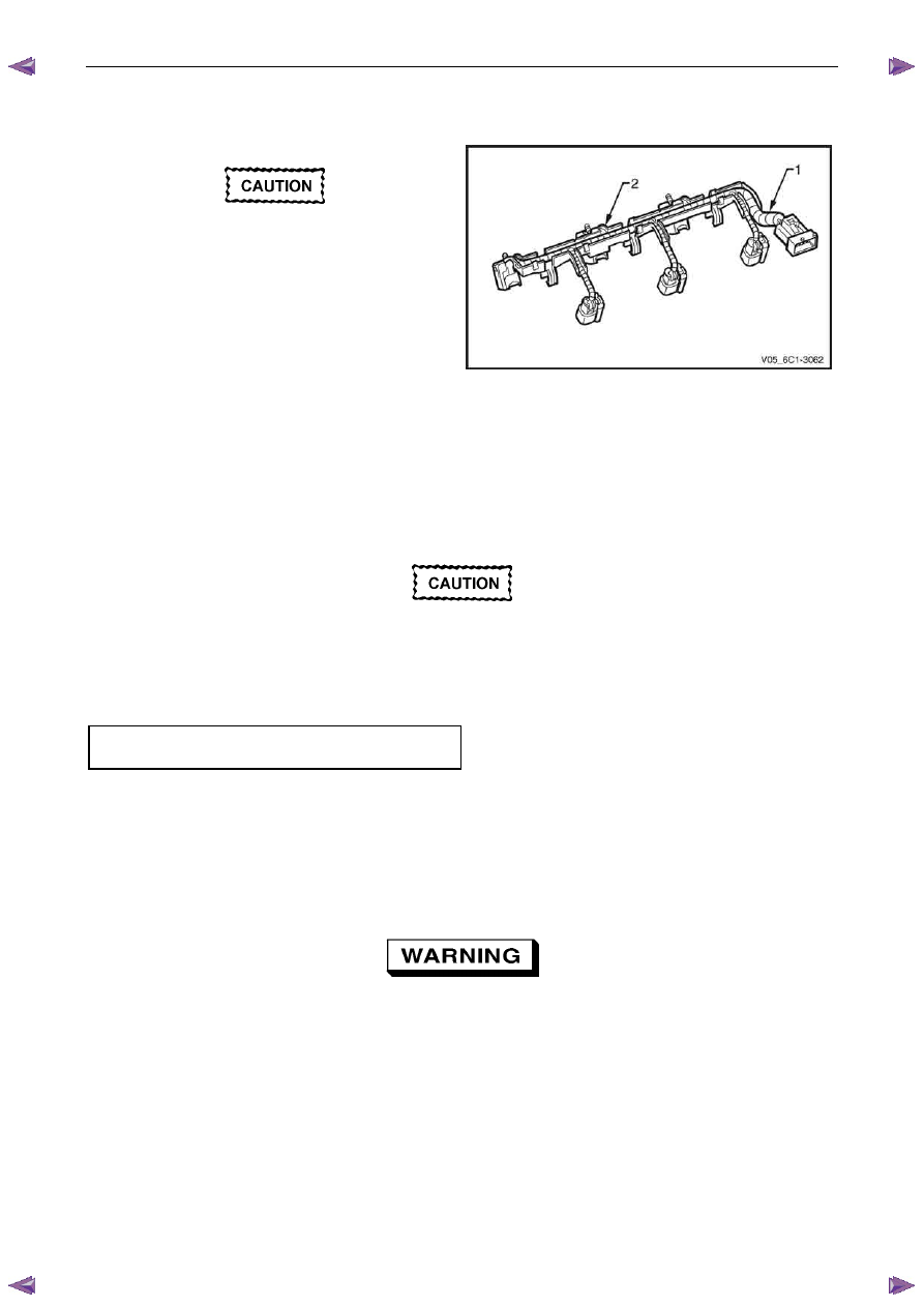
Reinstall
Reinstallation of the fuel injector wiring harness assembly is the reverse of the removal procedure, noting the following:
Ensure there is no undue strain placed on the
fuel injector wiring harness (1) once it has
been positioned in the tray (2).
1
Lay the fuel injector wiring harness in the lower tray.
2
Clip the upper and lower fuel injector harness trays
together, ensuring that all eight retainers are correctly
seated.
Figure 6C1-3 – 41
Reinstall
Reinstallation of the fuel rail assembly is the reverse of the removal procedure, noting the following:
1
Lubricate the fuel injector O-rings with engine oil.
2
Carefully reinstall the fuel rail and injector assembly.
Ensure the fuel injectors are correctly seated
in the lower intake manifold, and the fuel rail
attaching brackets are correctly located prior
to tightening the attaching bolts.
3
Reinstall the fuel rail attaching bolts and tighten to the correct torque specification.
Fuel rail attaching bolt
torque specification . . . . . . . . ..8.0 – 12.0 Nm
4
Reconnect the fuel feed hose to the fuel rail, refer to 6C Fuel System - V6.
5
Inspect the fuel rail and quick connect fitting for leaks, refer to 6C Fuel System - V6.
6
Road test the vehicle and check for correct operation.
2.14 Heated Oxygen Sensor
To avoid the possibility of personal injury,
allow the exhaust pipe to cool to ambient
temperature (less than 50
°°°°C) before
attempting to remove the oxygen sensor.
Service Precautions
•
Handle the HO2S carefully. Do not drop it, and keep it free of grease, dirt and other contaminants. Do not use
cleaning solvents of any type on the HO2S.
•
Do not repair the HO2S or any of its parts. Replace the HO2S if any damage is evident.
•
The HO2S may be difficult to remove when the engine is cold. Excessive force may damage the threads in the
exhaust manifold or exhaust pipe.
Engine Management – V6 – Service Operations
Page 6C1-3–34
•
If the HO2S has been removed, but not replaced, anti-seize compound must be applied to the threads prior to
installation. New HO2S will already have the anti-seize compound applied.
•
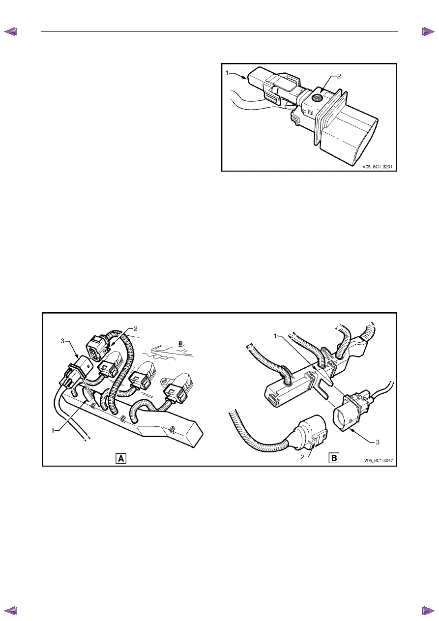
For vehicles with the six wire HO2S sensor, under no
circumstances should the protective cover (1) be
removed, or the gortex filter (2) be covered and / or
sealed.
Figure 6C1-3 – 42
Six Wire Sensor
The replacement procedure for Bank 1 and Bank 2 six wire heated oxygen sensor (HO2S) are typically the same, with
the following procedure being specific to Bank 1.
Remove
1
Turn the ignition switch off.
2
Unclip the HO2S wiring harness connector assembly (1) from the ignition coil wiring harness tray, refer to Figure
6C1-3 – 43. View A refers to Bank 1, and View B refers to Bank 2.
3
Slide the connector locking tang (2) away from the harness connector.
4
Separate the harness connector (3).
Figure 6C1-3 – 43
5
Raise the front of the vehicle and support on safety stands. Refer to 0A General Information for location of the
jacking points.
Engine Management – V6 – Service Operations
Page 6C1-3–35
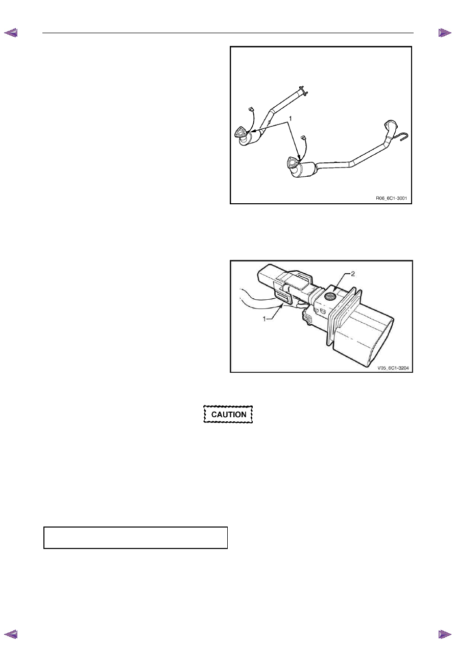
6
Unscrew the HO2S (1) from the exhaust pipe and
remove.
7
If required, test the HO2S, refer to the Test in this
Section.
Figure 6C1-3 – 44
Reinstall
Reinstallation of the heated oxygen sensor (HO2S) is the reverse of the removal procedure, noting the following:
1
Ensure the protective cover (1) is securely in place,
and the gortex filter (2) has not been covered or
sealed.
Figure 6C1-3 – 45
A special anti-seize compound is used on the
HO2S threads. A new HO2S will already have
the anti-seize compound applied to the
threads.
If a HO2S has been removed, but not replaced,
an anti-seize compound must be applied to
the threads prior to installation.
2
Coat the cleaned threads of the HO2S with anti-seize compound.
3
Tighten the HO2S to the correct torque specification.
Heated oxygen sensor
torque specification . . . . . . . . .40.0 – 50.0 Nm
4
Road test the vehicle and check for correct operation, taking particular note that no exhaust leakage is evident.
Four Wire Sensor
The replacement procedure for Bank 1 (RHS) and Bank 2 (LHS) four wire heated oxygen sensor (HO2S) are typically the
same, with the following procedure being specific to Bank 2.
Нет комментариевНе стесняйтесь поделиться с нами вашим ценным мнением.
Текст