Isuzu KB P190. Manual — part 887
Engine Management – V6 – Service Operations
Page 6C1-3–24
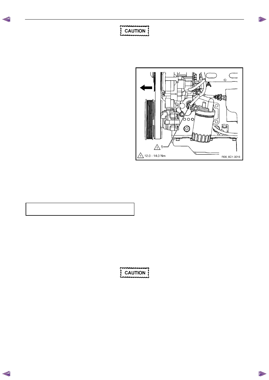
Clean the area around the engine oil pressure
sensor before removal to avoid debris from
entering the engine.
2
Disconnect the wiring harness connector (1) from the engine oil pressure sensor.
N O T E
A small amount of oil will drain from the oil filter
housing when the engine oil pressure sensor is
removed. Use a shop towel to absorb the oil.
3
Using special tool J 41712 or a 11/16" deep socket
and socket bar, remove the engine oil pressure
sensor (1).
Figure 6C1-3 – 22
Reinstall
Reinstallation of the engine oil pressure sensor is the reverse of the removal procedure, noting the following:
1
Tighten the engine oil pressure sensor to the correct torque specification.
Engine oil pressure sensor
torque specification . . . . . . . . .12.0 – 14.0 Nm
2
Check the engine oil level and top up if necessary, refer to 6A1 Engine Mechanical – V6.
2.11 Evaporative Emission (EVAP) Canister
Purge Valve Quick Connect Fittings
Disconnect
Clean the area around the evaporative
emission (EVAP) canister purge valve before
disconnecting the quick connect fitting to
avoid debris from entering EVAP canister
purge valve.
Engine Management – V6 – Service Operations
Page 6C1-3–25
Locking Lever Type
1
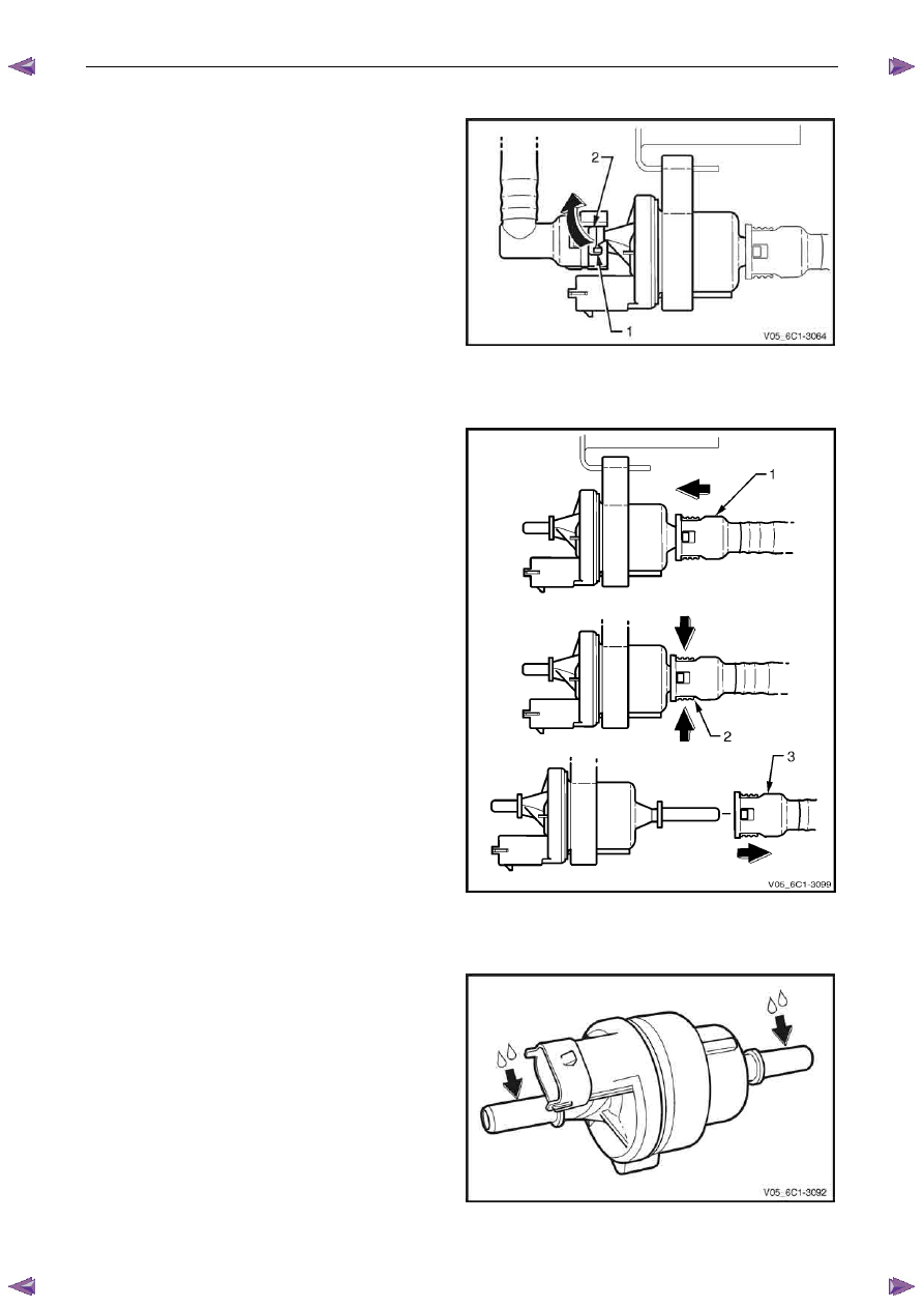
Rotate the quick connect locking lever (1) in the
direction of the arrow.
2
Whilst holding the lever against its stop (2), pull the
hose away from the EVAP canister purge valve.
Figure 6C1-3 – 23
Latch Type
1
Push the quick connect fitting (1) in the direction of
arrow.
2
Whilst pressing the two latches (2) in the direction of
the arrows, pull the quick connect fitting (3) away from
the EVAP canister purge valve.
Figure 6C1-3 – 24
Connect
1
Lubricate the evaporative emission (EVAP) canister
purge valve with clean engine oil.
Figure 6C1-3 – 25
Engine Management – V6 – Service Operations
Page 6C1-3–26
2
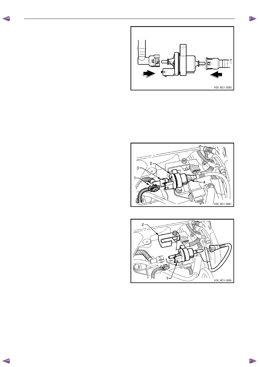
Push the hose quick connect fitting onto the purge
valve fitting. There will be an audible click as the quick
connect fitting engages.
3
Check the locking lever has returned to its rest
position.
4
Check the quick connect fittings have fully engaged by
gently pulling the quick connect fitting away from the
purge valve.
Figure 6C1-3 – 26
2.12 Evaporative Emission Canister Purge
Valve
Remove
1
Turn the ignition switch off.
2
Disconnect the wiring harness connector (1) from the
evaporative emission (EVAP) canister purge valve (2).
3
Disconnect the two EVAP canister purge valve hoses
(3 and 4), refer to 2.11
Evaporative Emission
(EVAP) Canister Purge Valve Quick Connect Fittings.
Figure 6C1-3 – 27
4
Slide the EVAP canister purge valve (1) from the
purge valve mounting bracket (2).
5
If required, test the EVAP canister purge valve, refer to
the Test in this Section.
Figure 6C1-3 – 28
Engine Management – V6 – Service Operations
Page 6C1-3–27
Test
To prevent component damage:
• Use connector test adaptor kit J 35616-A.
• When applying 12 V to a component,
always use a 3 A fused wire.
Resistance Check
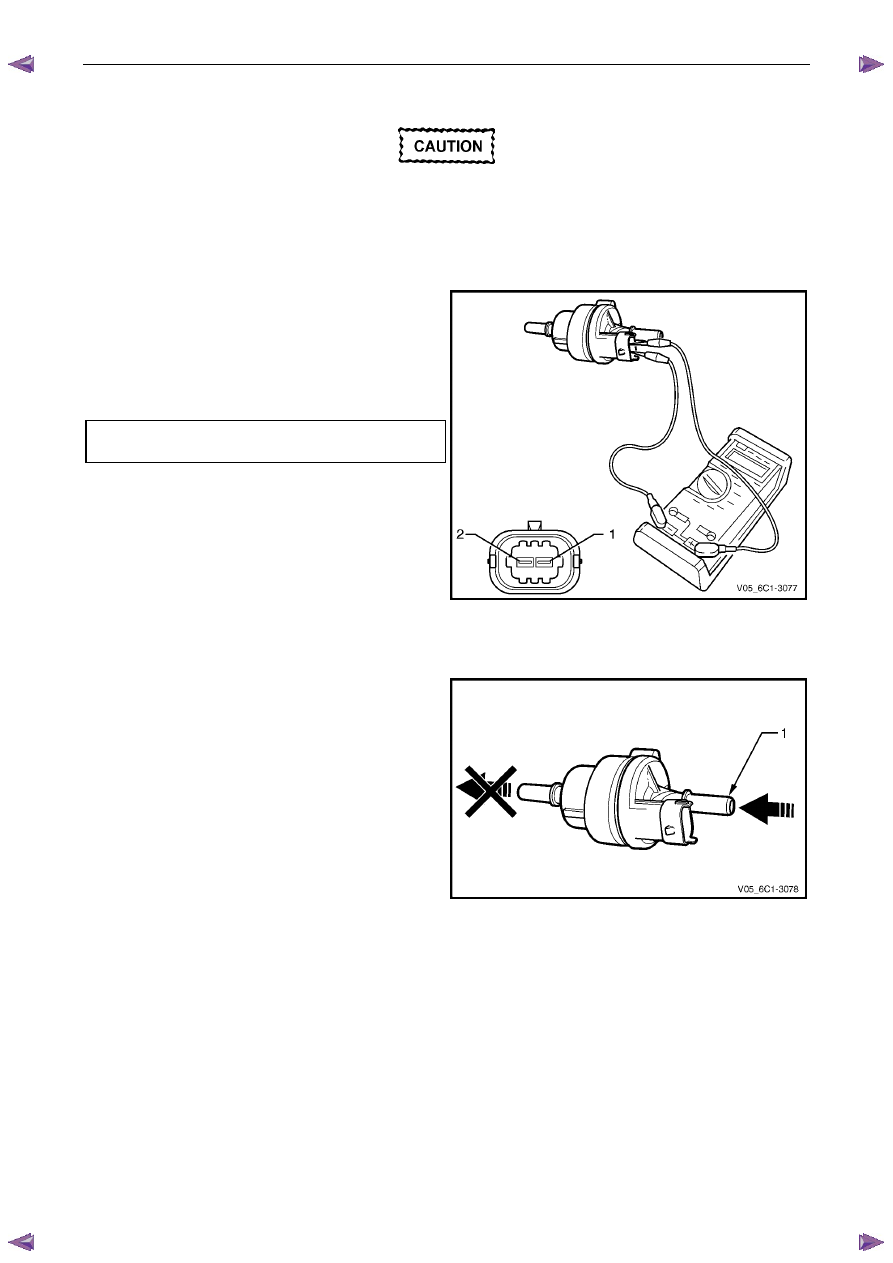
1
Using a digital ohmmeter and connector test adaptor
kit J 35616-A, measure the resistance across
terminals 1 and 2.
2
Compare the reading against the specification.
3
If the resistance is not within specification, replace the
EVAP canister purge valve.
EVAP canister purge valve
resistance @ 20°C . . . . . . . . . 24.0 – 28.0
Ω
Figure 6C1-3 – 29
Functional Test
1
Attempt to blow air through the EVAP canister purge
valve inlet port (1). If air passes through the valve, the
valve is faulty and should be replaced.
Figure 6C1-3 – 30
Нет комментариевНе стесняйтесь поделиться с нами вашим ценным мнением.
Текст