Isuzu KB P190. Manual — part 983
Automatic Transmission – 4L60E – On-vehicle Servicing
Page 7C4–19
Reinstall
1
Lubricate a new O-ring seal with petroleum jelly and install it to the vehicle speed sensor.
2
Install the speed sensor to the transmission extension housing.
3
Install the attaching bolt and tighten to the correct torque specification.
Vehicle speed sensor attaching bolt
torque specification . . . . . . . . . . . 12.0 Nm
4
Connect the connector to the speed sensor.
5
Lower the vehicle to the ground.
3.6
Manual Shaft Oil Seal
Replace
N O T E
This procedure requires the use of special tool
No. AU583.
1
Raise the vehicle and support in a safe manner, refer to 0A General Information for the location of support points.
2
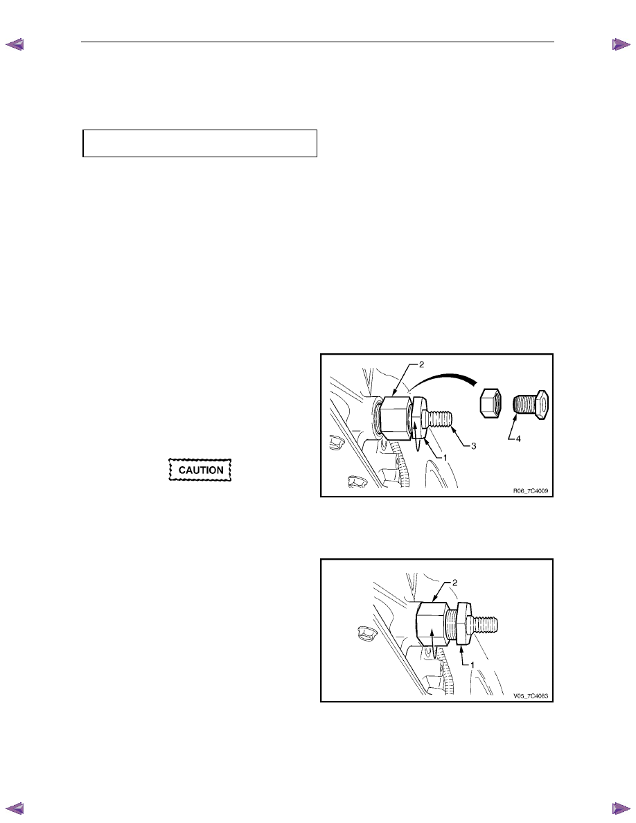
Remove the neutral start and back-up lamp switch, refer to 3.4
Neutral Start and Back-up Lamp Switch.
3
Assemble the seal remover, Tool No. AU583-3 (1) by
installing the remover nut, Tool No. AU583-4 (2) with
its threaded inner diameter closest to the hexagonal
head of the seal remover tool. Install the nut up to the
hexagonal head.
4
Install the assembled seal remover tool over the
manual shaft (3) engaging the tapered thread end (4)
into the seal.
Do not over tighten the seal remover tool in
the seal.
5
Rotate the hexagonal head of the seal remover tool
clockwise, until the thread grips the steel shell of the
seal.
Figure 7C4 – 16
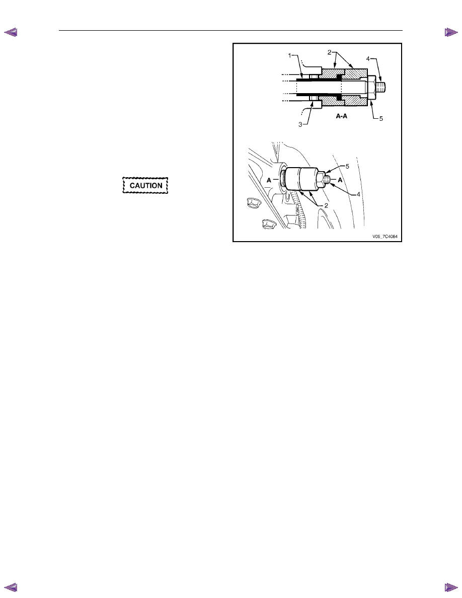
6
While holding the hexagonal head of the seal remover
tool (1) rotate the remover nut (2) clockwise, until it
contacts the transmission case.
7
Continue rotating the remover nut until the seal is
pulled into the remover nut cavity.
8
Remove and discard the seal.
Figure 7C4 – 17
Automatic Transmission – 4L60E – On-vehicle Servicing
Page 7C4–20
9
Install the seal protector, Tool No. AU583-1 (1) into
one of the two plastic seal installers, Tool No.
AU583-2 (2).
N O T E
Two plastic seal installers are required because
of the restricted space between the end of the
manual shaft and the floor pan.
10
Lubricate the lip of a new seal (3) with clean automatic
transmission fluid and install it over the seal protector
sleeve, with the steel casing facing the installer tool.
11
Install the seal protector with the new seal and installer
tool over the manual shaft (4) and up to the
transmission case.
If the seal protector sleeve jams on the
manual shaft, the flats on the shaft locating
the selector lever will be burred. Use a fine
file to remove any burrs and then proceed.
12
Fit the second plastic seal installer over the manual
shaft until it seats against the first installer.
13
Install the manual shaft linkage attaching nut (5) and
tighten it to drive the seal in position into the
transmission case.
14
Remove the seal installer and protector tools from the
manual shaft.
Figure 7C4 – 18
15
Reinstall the neutral start and back-up lamp switch, refer to 3.4
Neutral Start and Back-up Lamp Switch.
16
Lower the vehicle to the ground and as required, check and top up the automatic transmission fluid level, refer to
2.1 Transmission Fluid.
3.7
Transmission Support and Mount
Remove
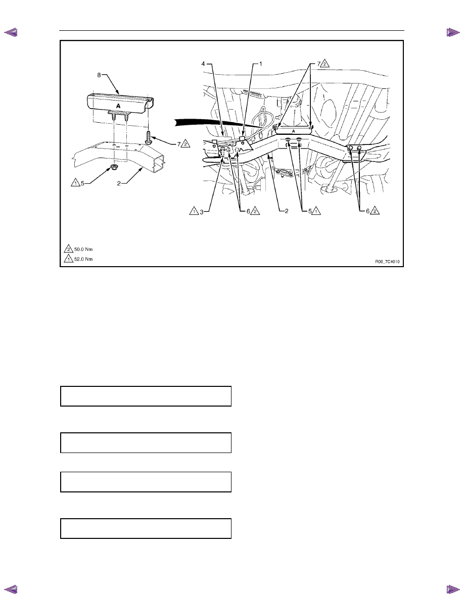
1
Raise the vehicle and support in a safe manner, refer to 0A General Information for the location of support points.
2
Support the transmission with a Jack, do not place the support underneath the extension housing or the oil pan,
refer to Figure 7C4 – 19.
3
Remove the clip (1) holding the fuel feed and fuel vapour lines on the transmission support (2).
4
Remove the bolt (3) attaching the heat shield (4) to the transmission support.
5
Remove the two nuts (5) attaching the transmission mount to the support.
6
Remove the four bolts and nuts (6) attaching the transmission support to the under body side rails and remove the
support.
7
If required, remove the two bolts (7) attaching the transmission mount (8) to the extension housing and remove the
mount.
Automatic Transmission – 4L60E – On-vehicle Servicing
Page 7C4–21
Figure 7C4 – 19
Legend
1
Fuel Feed and Vapour Lines Clip
2 Transmission
Support
3 Heat
Shield
Bolt
4 Heat
Shield
5
Transmission Mount Nuts
6
Transmission Support Bolts
7
Transmission Mount Bolts
8 Transmission
Mount
Reinstall
1
If required, install the transmission mount (8) onto the extension housing, tighten the two attaching bolts (7) to the
correct torque specification, refer to Figure 7C4 – 19.
Transmission mount attaching
bolt torque specification . . . . . . . . . .50.0 Nm
2
Install the transmission support (2) to the under body side rails and tighten the four attaching bolts and nuts (6) to
the correct torque specification.
Transmission support attaching
bolt and nut torque specification . . . . . . 50.0 Nm
3
Install and tighten the transmission mount two attaching nuts (5) to the correct torque specification.
Transmission mount attaching
nut torque specification . . . . . . . . . ..52.0 Nm
4
Install the bolt (3) attaching the heat shield (4) to the transmission support, tighten to the correct torque
specification.
Heat shield to transmission support
attaching bolt torque specification. . . . . ..52.0 Nm
5
Reinstall the clip (1) holding the fuel feed and fuel vapour lines on the transmission support.
6
Lower the vehicle to the ground.
Automatic Transmission – 4L60E – On-vehicle Servicing
Page 7C4–22
3.8
Extension Housing Oil Seal, RWD
Replace
1
Raise the vehicle and support in a safe manner, refer to 0A General Information for the location of support points.
2
Remove the rear propeller shaft, refer to 4A Propeller Shaft.
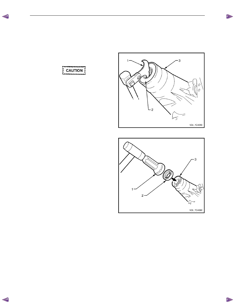
3
Place a suitable size drip tray underneath rear of
transmission.
Take care not to scratch the machined seal
recess in the extension housing as
transmission fluid may weep past the outer
diameter of the installed seal.
4
Using the seal remover, Tool No. E308 (1) or
equivalent, prise the oil seal (2) from rear of the
extension housing (3) and discard the seal.
5
Thoroughly clean around the seal bore in the
extension housing and ensure there are no burrs.
Figure 7C4 – 20
6
Use the seal installer, Tool No. J21426 (1) and a soft
faced hammer to tap a new oil seal (2) into place in
the extension housing (3).
7
Install the rear propeller shaft, refer to 4A Propeller
Shaft.
8
Lower the vehicle to the ground and check the fluid
level, refer to 2.1
Transmission Fluid.
Figure 7C4 – 21
3.9
Extension Housing and Rear Bush, RWD
Remove
1
Raise the vehicle and support in a safe manner, refer to 0A General Information for the location of support points.
2
As required, remove the following components:
a
Rear propeller shaft, refer to 4A Propeller Shaft.
b
Transmission support and mount assembly, refer to 3.7
Transmission Support and Mount.
c
Vehicle speed sensor, refer to 3.5 Vehicle Speed Sensor.
Нет комментариевНе стесняйтесь поделиться с нами вашим ценным мнением.
Текст