Isuzu KB P190. Manual — part 982

Automatic Transmission – 4L60E – On-vehicle Servicing
Page 7C4–15
Remove
1
Remove the front and rear console, refer to 10 Cab.
2
Position the transmission selector lever to the N position.
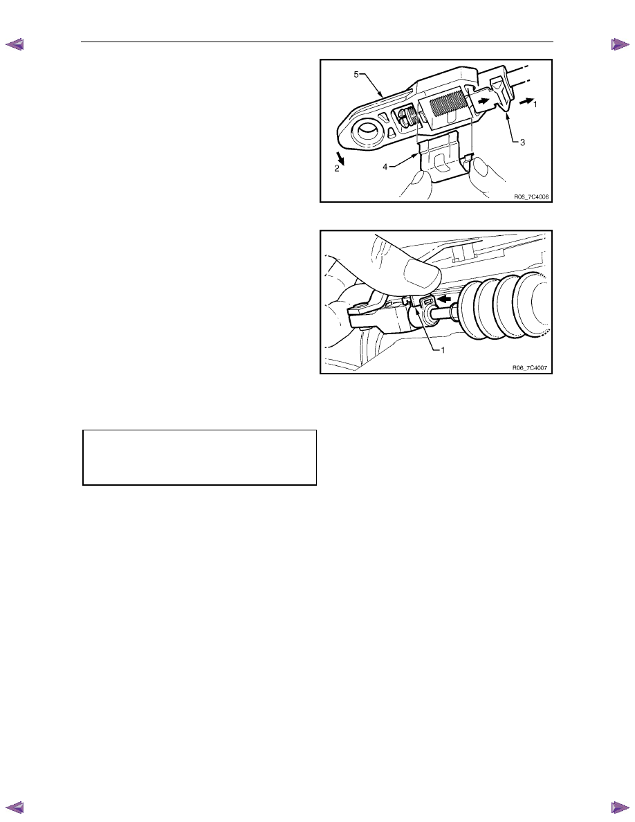
3
Using a small flat blade screwdriver, gently prise the upper end of the selector cable (1) from the pin on the selector
lever linkage (2), refer to Figure 7C4 – 10.
4
Press on the selector cable retaining pawl (3) to remove the cable from the shift selector base plate (4).
5
Raise the vehicle and support in a safe manner, refer to 0A General Information for the location of support points.
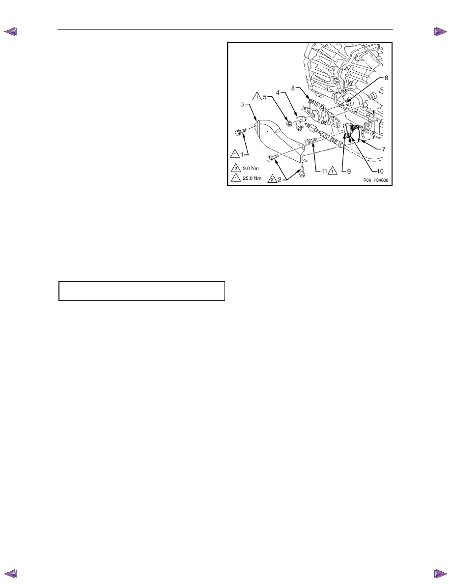
6
Remove the three attaching screws (5 and 6) and the heat shield (7).
7
Using a small flat blade screwdriver, gently prise the transmission end of the selector cable from the transmission
external manual shaft linkage (8).
8
Remove the clip and selector cable from the bracket (9).
9
Pull the selector cable free from the bottom of the vehicle.
10
If required, remove the two attaching bolts (10) and the selector cable bracket.
Reinstall
1
Install the selector cable (1) toward the inside of the cabin from under the vehicle, refer to Figure 7C4 – 10.
2
Push the end of the selector cable into the shift selector base plate (4).
3
Attach the end of the selector cable to the pin on the selector lever linkage (2).
4
If required, install the selector cable bracket (9), tighten the two attaching bolts (10) to the correct torque
specification.
Selector cable bracket attaching
bolt torque specification . . . . . . . . . .22.0 Nm
5
Fit the selector cable to the bracket and install the clip on the marking of the selector cable.
6
Ensure the selector lever is in the N position.
7
Ensure the transmission external manual shaft
linkage (8) is in the N position.
Figure 7C4 – 11
Automatic Transmission – 4L60E – On-vehicle Servicing
Page 7C4–16
8
Slide the cover (3) in the direction shown by the
arrow (1).
9
Using a small flat blade screwdriver, move the lock
piece (4) from the position indicated by the arrow (2).
Continue to move the lock piece until the adjuster (5)
position begins to change.
Figure 7C4 – 12
10
Connect the selector cable to the transmission
external manual shaft linkage.
11
Insert the lock piece in the adjuster to engage with the
serrated cable end (cable length adjustment).
12
Slide the cover (1) on the adjuster and secure the lock
piece.
Figure 7C4 – 13
13
Install the heat shield (7) and tighten the attaching screws (1 and 6) to the correct torque specification, refer to
Figure 7C4 – 10.
Heat shield front attaching screw
torque specification . . . . . . . . . . . 25.0 Nm
Heat shield rear attaching screw
torque specification . . . . . . . . . . . ..9.0 Nm
14
Move the selector lever to the P position and press the selector lever knob button five times.
15
Ensure the selector lever moves smoothly to each of its positions.
16
Check if the shift position indicated by the selector lever and the actual shift position are the same, rectify if
required.
17
Lower the vehicle to the ground. Ensure the engine can only be started with the transmission selector lever in Park
or Neutral position and the back-up lamps work correctly. If required, adjust the neutral start and back-up lamp
switch, refer to 3.4
Neutral Start and Back-up Lamp Switch.
18
Ensure the gear selection operates correctly.
19
Install the front and rear console, refer to 10 Cab.
3.4
Neutral Start and Back-up Lamp Switch
Remove
1
Position the transmission selector lever to the P position.
2
Raise the vehicle and support in a safe manner, refer to 0A General Information for the location of support points.
Automatic Transmission – 4L60E – On-vehicle Servicing
Page 7C4–17
3
Remove the three attaching screws (1 and 2) and the
heat shield (3).
4
Hold the transmission manual shaft linkage (4) with an
adjustable wrench and remove the linkage attaching
nut (5).
5
Carefully remove the manual shaft linkage and
selector cable from the transmission manual shaft (6).
6
Prise the connector position assurance (CPA)
securing pin (7) from the neutral start and back-up
lamp switch (8) taking care not to break the pin in the
process. Disconnect the connector (9) from the switch
assembly by pulling down the release bar (10).
N O T E
The connector will automatically disconnect at
the same time the release bar is withdrawn.
7
Remove the attaching screw (11) and slide the switch
assembly over the transmission manual shaft to
remove it.
Figure 7C4 – 14
Reinstall
1
Slide the neutral start and back-up lamp switch (8) over the transmission manual shaft (6) and reinstall the two
attaching screws (1 and 11), tighten them finger tight until the adjustment process has been completed, refer to
Figure 7C4 – 14.
2
Install the manual shaft linkage (4) and the attaching nut (5). Hold the linkage with an adjustable wrench and
tighten the nut to the correct torque specification.
Manual shaft linkage attaching nut
torque specification . . . . . . . . . . . 25.0 Nm
3
Install the connector (9) but do not reinsert the CPA securing pin (7) at this stage.
4
Check the shift selector linkage operation and adjust as required, refer to 3.2
Shift Selector Assembly.
5
Check and adjust as required the neutral start and back-up lamp switch as described in this Section, refer to Adjust.
Adjust
1
Raise the vehicle and support in a safe manner, refer to 0A General Information for the location of support points.
2
If required, loosen the neutral start and back-up lamp switch (8) as follows, refer to Figure 7C4 – 14:
a
Remove the three attaching screws (1 and 2) and the heat shield (3).
b
Prise the connector position assurance (CPA) securing pin (7) from the neutral start and back-up lamp switch
taking care not to break the pin in the process.
c
Disconnect connector (9) from the switch assembly by pulling down the release bar (10).
N O T E
The connector will automatically disconnect at the
same time the release bar is withdrawn.
d
Loosen the screw (11) attaching the switch and refit the front screw (1) keep them finger tight.
e
Reinstall the connector (9) but do not reinsert the CPA securing pin at this stage.
3
Rotate the neutral start and back-up lamp switch back and forth until a central position is attained and then lightly
tighten the front screw (1) to prevent the switch from rotating.
Automatic Transmission – 4L60E – On-vehicle Servicing
Page 7C4–18
Ensure the four wheels are off the ground
before performing the starting test.
4
With the ignition switched to the ON position, check if the engine can only be started in the Park and Neutral shift
selector positions and ensure the back-up lamps illuminate when Reverse is selected. A further minor adjustment
may be required to achieve this state.
N O T E
To gain access to the rear attaching screw (11) it
will be necessary to remove the connector.
5
After the switch has been adjusted, tighten the rear attaching screw (11) to the correct torque specification.
Neutral start and back-up lamp switch
attaching screw torque specification . . . . ..25.0 Nm
6
Reinstall the connector and the CPA securing pin.
7
Remove the switch front attaching screw (1).
8
Install the heat shield (3) and tighten the attaching screws (1 and 2) to the correct torque specification.
Heat shield front attaching screw
torque specification . . . . . . . . . . . 25.0 Nm
Heat shield rear attaching screw
torque specification . . . . . . . . . . . ..9.0 Nm
9
Lower the vehicle to the ground and re-check the operation of the neutral start and back-up lamp switch. The
vehicle must start only with the shift selector in the Park or Neutral positions and the back-up lamps should only
illuminate when Reverse is selected.
3.5 Vehicle
Speed
Sensor
N O T E
For the speed sensor fitted to four wheel drive
vehicles (4WD), refer to 7D Transfer Case and
Adaptor Housing.
Remove
1
Raise the vehicle and support in a safe manner, refer
to 0A General Information for the location of support
points.
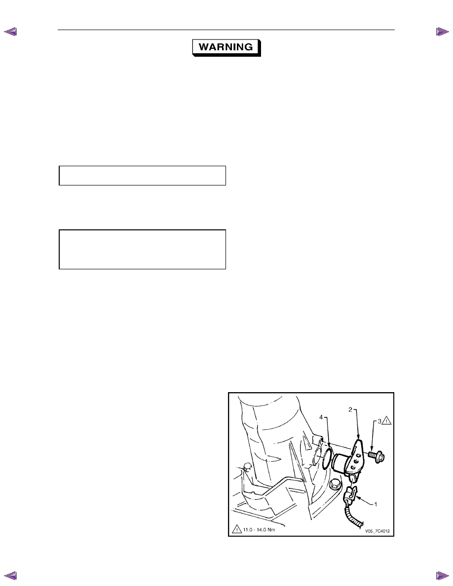
2
Disconnect connector (1) from the vehicle speed
sensor (2).
3
Remove the bolt (3) attaching the speed sensor to the
transmission extension housing.
4
With a pulling and turning motion, remove the speed
sensor and O-ring seal (4) from the transmission
extension housing, discard the O-ring.
Figure 7C4 – 15
Нет комментариевНе стесняйтесь поделиться с нами вашим ценным мнением.
Текст