Isuzu KB P190. Manual — part 255
ENGINE ELECTRICAL 6D – 19
RTW46DSH000401
Important Operations
2. Rear rotor bearing
• Re-use improper parts.
5. Rectifier
6. Stator
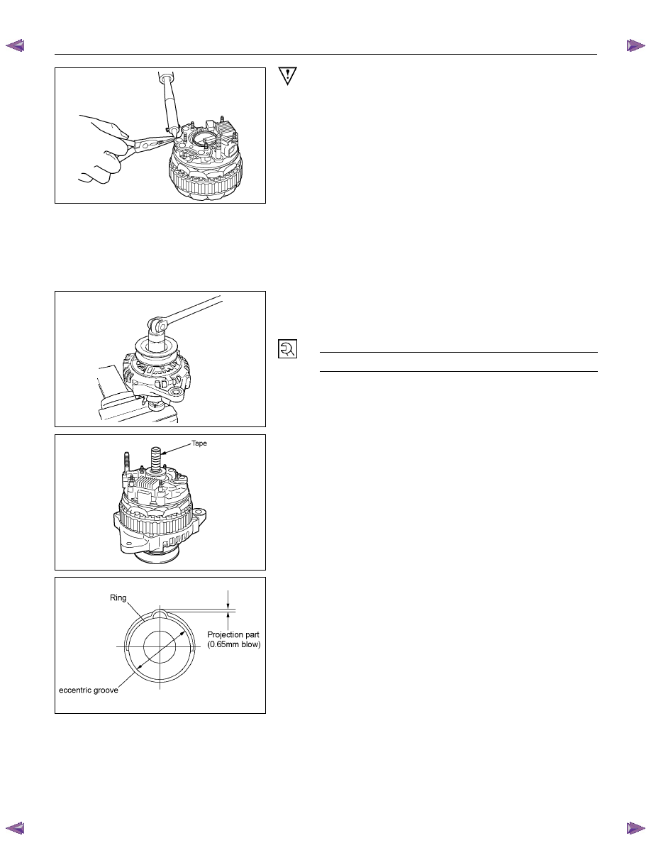
Use a pair of long-nose plier to connect the stator coil
leads and the rectifier leads.
Finish the work as quickly as possible to prevent the
rectifier from heat transferred by the soldering.
RTW46DSH002101
3. Rotor
Assembly
4. Pulley
Assembly
Clamp the rotor in a vise and install the pulley nut.
Pulley Nut Torque
N
⋅m (kg⋅m/lb⋅ft)
83.3
∼ 98.0 (8.5 ∼ 10.0 / 61 ∼ 72)
RTW46DSH006001
Remove the tape from the splines.
RTW46DSH004901
The rear ball bearing is pressed into the wheel eccentric
groove. The bearing ring projects from the groove.
During installation, rotate the bearing to the point of
minimum bearing ring projection.
Inspect the rear cover bearing box and replace it if it is
damaged.
6D – 20 ENGINE ELECTRICAL
RTW46DSH002201
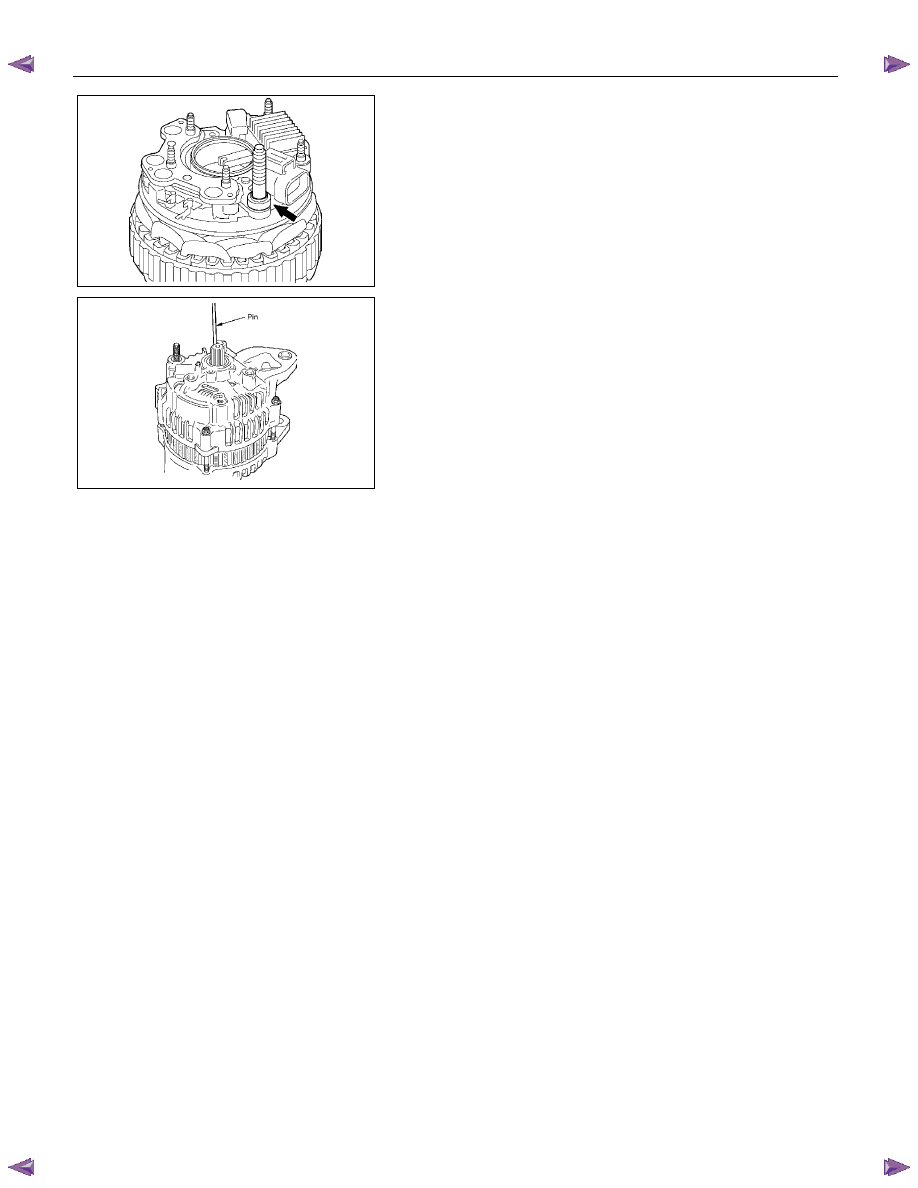
NOTE: Be sure to attach a cooler to B terminal.
RTW46DSH005301
Insert the pin from the outside of the rear cover. Press the
brushes into the brush holder. Complete the assembly
procedure.
Remove the pin after completion of the assembly
procedure.

ENGINE ELECTRICAL 6D – 21
RTW06DSH000201
9. Through
Bolt
1. Place a pilot bar into the through bolt hole to align the
front cover and the rear cover.
2. Install the through bolts and tighten them to the
specified torque.
Through Bolt Torque
N
⋅m (kg⋅m/lb⋅ft)
3.1
∼ 3.9 (0.32 ∼ 0.41 / 2.6 ∼ 3.5)
11. Vaccum Pump
To install the generator -
1. Note the direction of the arrow on the vacuum pump.
2. Look forward from the base of the arrow to locate the
3 generator fixing points.
3. Twist the fixing points down and to the left to align
them with the middle of the center plate and the rotor.
RTW46DSH006101
Install vanes into slits in rotor.
The vanes should be installed with the chamfered side
facing outward.
RTW46DSH002401
Install the vacuum pump housing.
Make sure that the O-ring is not projecting beyond the
slots of the center plate.
Take care so that no scratching takes place on the vane
resulted by contact with the housing.
RTW46DSH002501
Install the housing in the generator and fix it with the three
bolts.
Supply engine oil (5cc or so) from the oil port and check
that the generator pulley can be turned smoothly with your
hand.
Generator Housing Bolt Torque
N
⋅m (kg⋅m/lb⋅ft)
5.9
∼ 6.9 (0.6 ∼ 0.7 / 5.2 ∼ 6.1)
6D – 22 ENGINE ELECTRICAL
STARTER MOTOR
REMOVAL AND INSTALLATION
Read this Section carefully before performing any removal and installation procedure. This Section gives you
important points as well as the order of operation. Be sure that you understand everything in this Section before you
begin.
Important Operations - Removal
Starter Motor
1. Disconnect the battery cable and the ground cable at
the battery terminals.
2. Disconnect the magnetic switch cable at the terminal
bolts.
3. Disconnect the battery cable at the starter motor and
the ground cable at the cylinder body.
4. Remove the starter motor from the engine.
Important Operations – Installation
Follow the removal procedure in the reverse order to
perform the installation procedure. Pay careful attention to
the important points during the installation procedure.
Starter Motor
1. Install the starter motor to the rear plate.
2. Tighten the starter motor bolts to the specified torque.
Starter Motor Bolt Torque
N
⋅m (kg⋅m/lb⋅ft)
85 (8.7/63)
3. Reconnect the battery cable at the starter motor and
the ground cable at the cylinder body.
4. Reconnect the battery cable and the ground cable at
the battery terminals.
Нет комментариевНе стесняйтесь поделиться с нами вашим ценным мнением.
Текст