Isuzu KB P190. Manual — part 518
6A-58 ENGINE MECHANICAL (C24SE)
Clean
Plastigage from journals.
Lightly coat journals and bearings with engine oil.
Installation
Install bearing cap and shell using new bolts.
Torque - Angle Method
Main bearing cap bolt - 60 N
⋅m (6.1 kgf⋅m) +40° to 50°.
Con-rod bearing cap bolts - 35 N
⋅m (3.9 kgf⋅m) +45°.
2.Micrometer and gauge method.
Crankshaft removed.
Installation
1. Install caps and bearing shells to con-rods and cylinder
block.
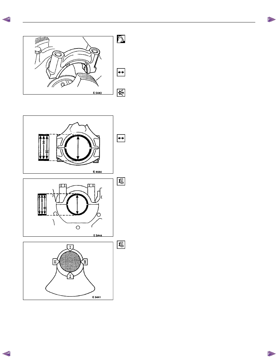
Measure
Con-rod and main bearing diameters at three points I, II, III
(arrowed).
Divide the sum of the three measurements by three to obtain a
mean diameter.
The top illustration shows con-rod measuring points.
The second illustration shows main bearing measuring points.
Measure
Crankshaft main and con-rod bearing journals at points I and
II. Divide the sum of both measurements to obtain a mean
diameter.
Crankshaft must be replaced if mean diameter of main or con-
rod journals is below specified limit - see "Technical Data".
If crankshaft is serviceable subtract crankshaft mean journal
diameters from corresponding shell bearing mean diameters to
determine bearing clearance.
Permissible main bearing clearance - 0.015 to 0.04mm/0.0006
to 0.002in.
Permissible con-rod bearing clearance - 0.006 to
0.031mm/0.002 to 0.001in.
ENGINE MECHANICAL (C24SE) 6A-59
Bypass Valve
Removal
1. Remove oil filter.
2. Remove bypass valve by cutting thread in locking disc
with M 10 tap (3rd stage), turning in M 10 bolt and taking
out bypass valve from seating.
Installation
1. Install bypass valve using drift (diameter approx.
15mm/0.6in.).
Oil Filter
Removal
1. Remove oil filter using commercially available tool.
Installation
1. Install oil filter by hand and oil seal ring.
2. Fill up engine oil while preventing overflow.
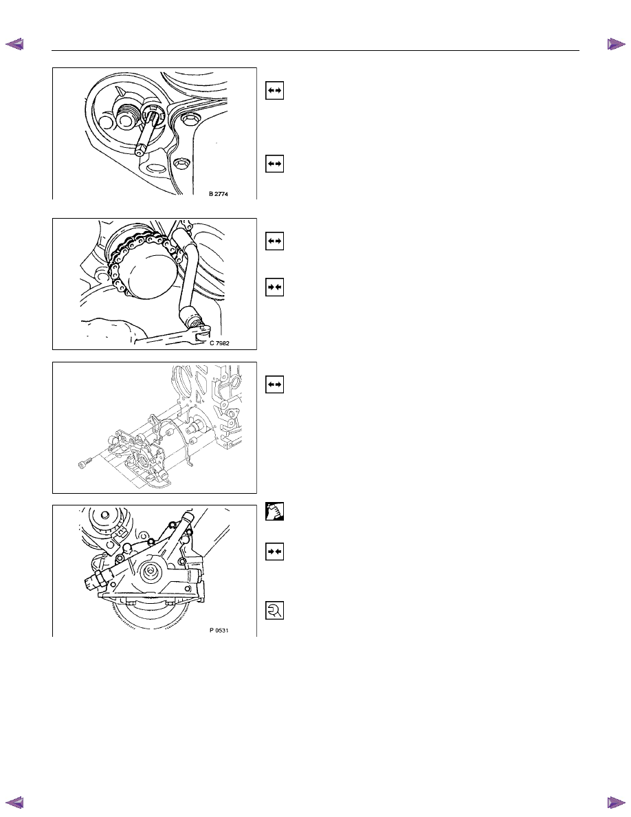
Oil Pump
Removal
1. Remove rear toothed belt cover, and oil pan according to
the corresponding operations.
2. Remove oil filter, wiring plug from oil pressure switch, oil
pump from cylinder block, and oil pressure switch from
oil pump.
Clean
Sealing surfaces
Installation
1. Install oil pressure switch to oil pump, oil pump to cylinder
block, oil pan, bearing bridge wiring plug, oil filter and
toothed belt cover.
Tighten (Torque)
Oil pressure switch to oil pump - 30 N
⋅m (3.2 kgf⋅m)
Oil pump to cylinder block - 6 N
⋅m (0.6 kgf⋅m)
Oil intake pipe to oil pump - 8 N
⋅m (0.8 kgf⋅m)
Intake pipe bracket to cylinder block - 8 N
⋅m (0.8 kgf⋅m)
*Insert bolts with Locktite (Refer to General Description
Recommended Liguid Gasket)

6A-60 ENGINE MECHANICAL (C24SE)
Oil Pump Safety Valve
Removal
1. Remove closure plug.
2. Remove seal ring.
3. Remove spring.
4. Remove piston.
Installation
1. Install piston (observe installation position).
2. Install spring.
3. Install seal ring.
4. Install closure plug.
Tighten (Torque)
Closure plug - 30 N
⋅m (3.0 kgf⋅m)
Oil Pump (Overhaul)
Removal
1. Remove oil pump according to the corresponding
operation.
2. Remove oil cover and pressure control valve.
Inspect
Clearance between gear pair and housing upper edge - see
“Technical Data”.
Check housing, cover and pressure control valve.
Installation
1. Install pump cover with Sealing Compound 15 03 166 (90
094 714).
2. Install oil pump safety valve according to the
corresponding operation.
3. Install oil pump according to the corresponding operation.
ENGINE MECHANICAL (C24SE) 6A-61
OPERATIONS ON OIL CIRCULATION
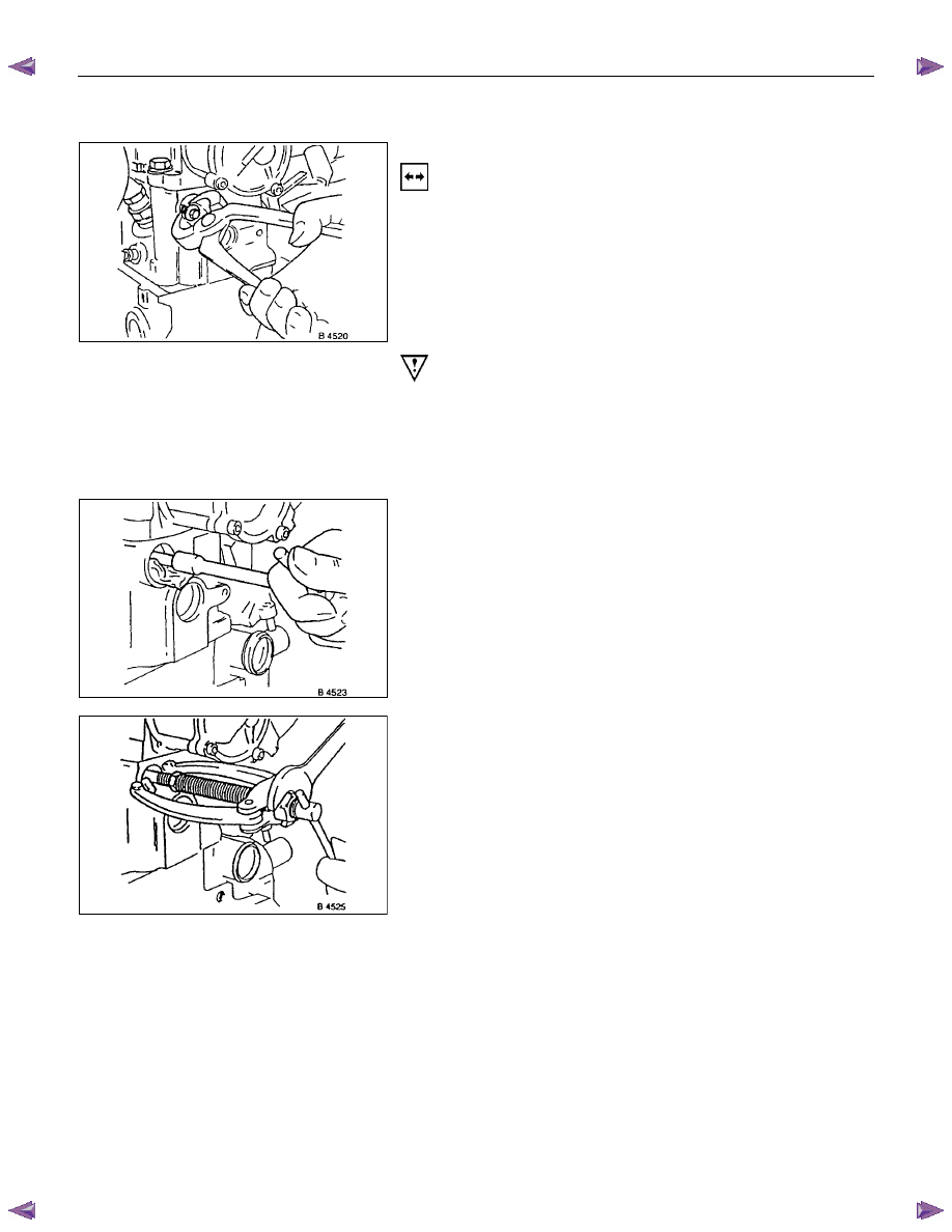
Cylinder Head Safety Valve
Removal
1. Remove cylinder head according to the corresponding
operation.
2. Make hole in core plugs with pointed drift, turn in self
tapping screw and edge out.
Important!
Cover oil duct in cylinder head with piece of cloth.
3. Pull out valve retainer, using commercially available tool.
4. Remove ball and spring.
5. Cut three threads in the ball seating with M 10 tap (3rd
stage).
6. Coat tap with grease.
7. Remove ball seating from cylinder head with
commercially available tool.
Do not damage cylinder head.
Нет комментариевНе стесняйтесь поделиться с нами вашим ценным мнением.
Текст