Isuzu KB P190. Manual — part 885

Engine Management – V6 – Service Operations
Page 6C1-3–16
2.6
Engine Coolant Temperature Sensor
Remove
To avoid serious personal injury, never
remove the engine coolant temperature (ECT)
sensor when the engine is hot. Allow the
engine to cool to ambient temperature (less
than 50
°°°°C) before performing this procedure.
1
Turn the ignition switch off.
To avoid serious personal injury, never
remove the coolant filler cap when the engine
is hot. Allow the engine to cool to ambient
temperature (less than 50
°°°°C) before
performing this procedure.
2
Allow the engine to cool to ambient temperature less than 50
°C, and slowly remove coolant filler cap located on the
coolant outlet housing.
3
Drain approximately two litres of coolant into a suitable container, refer to 6B1 – Engine Cooling – V6.
4
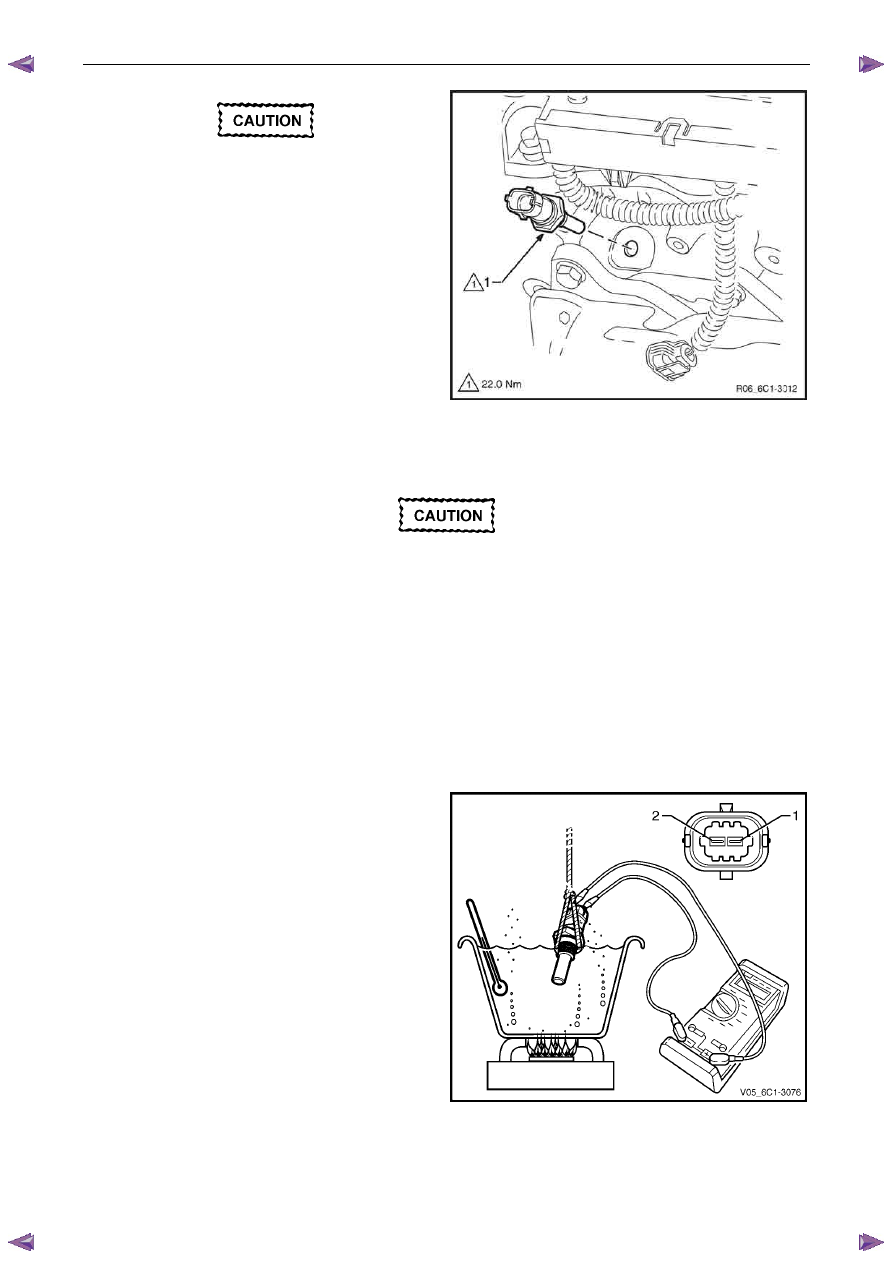
Disconnect the wiring harness connector (1) from the
ECT sensor (2).
Figure 6C1-3 – 12
Engine Management – V6 – Service Operations
Page 6C1-3–17
Clean the area around the ECT before
removal to avoid debris from entering the
engine.
5
Remove the ECT sensor (1).
N O T E
If coolant leaks from the cylinder head as the
sensor is removed, screw the sensor back into
the cylinder head and drain more coolant from
the cooling system.
6
If required, test the ECT sensor, refer to the Test in
this Section.
Figure 6C1-3 – 13
Test
To prevent component damage, use
connector test adaptor kit J 35616-A.
Resistance Check
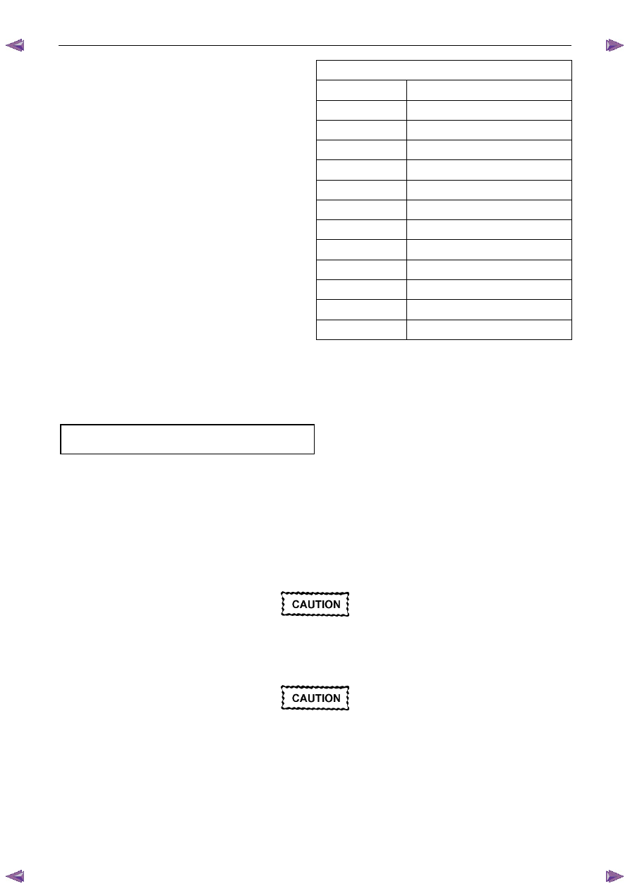
1
Suspend the engine coolant temperature (ECT) sensor and a suitable thermometer in a container of 50/50 DEX-
COOL® long life coolant or equivalent and water.
N O T E
Neither the ECT sensor or thermometer should
rest on the bottom of the container due to an
uneven concentration of heat at this point when
the container is heated.
2
Connect a digital ohmmeter using connector test
adaptor kit J 35616-A to the ECT sensor.
3
Measure the resistance across terminals 1 and 2.
4
Whilst heating the container, observe the resistance
values as the temperature increases and compare the
temperature / resistance change to the specifications.
Figure 6C1-3 – 14
Engine Management – V6 – Service Operations
Page 6C1-3–18
5
If the resistance is not within specifications, replace
the ECT sensor.
Engine Coolant Temperature Vs Resistance
Temperature °C
Resistance – Ohms (
Ω)
-40
40490 – 50136
-20
14096 – 16827
-10
8642 – 10152
0
5466 – 6326
20
2351 – 2649
25
1941 – 2173
40
1118 – 1231
60
573 – 618
80
313 – 332
100
182 – 191
120
109 – 116
140
68 – 74
Reinstall
Reinstallation of the engine coolant temperature (ECT) sensor is the reverse of the removal procedure, noting the
following:
1
Tighten the ECT sensor to the correct torque specification.
Engine coolant temperature sensor
torque specification . . . . . . . . . . . 22.0 Nm
2
Refill the cooling system, refer to 6B1 Engine Cooling – V6.
3
Road test the vehicle and check for correct operation, taking particular note there is no coolant leakage.
2.7
Engine Control Module
Service of the engine control module (ECM) should normally consist of either replacement or ECM programming. If the
diagnostic procedures call for the ECM to be replaced, it should be first checked to ensure it is the correct part. If it is,
replace the faulty ECM.
Do not touch the ECM connector pins as
electrostatic discharge (ESD) damage may
result.
When removing or reinstalling the ECM wiring
harness connector/s, ensure the ignition
switch is in the OFF position and the battery
has been disconnected. Failure to do so may
result in damage to the ECM and / or
associated componentry.
Disconnection of the battery affects certain
vehicle electronic systems. Refer to 6D1-3
Battery - V6 before disconnecting the battery.
Engine Management – V6 – Service Operations
Page 6C1-3–19
Remove
If replacing the ECM, it must be reset prior to
removal. Failure to perform this procedure
will result in the inability to test the ECM for
warranty purposes, refer to ECM Reset in this
Section.
1
Turn the ignition switch off.
2
Disconnect the battery.
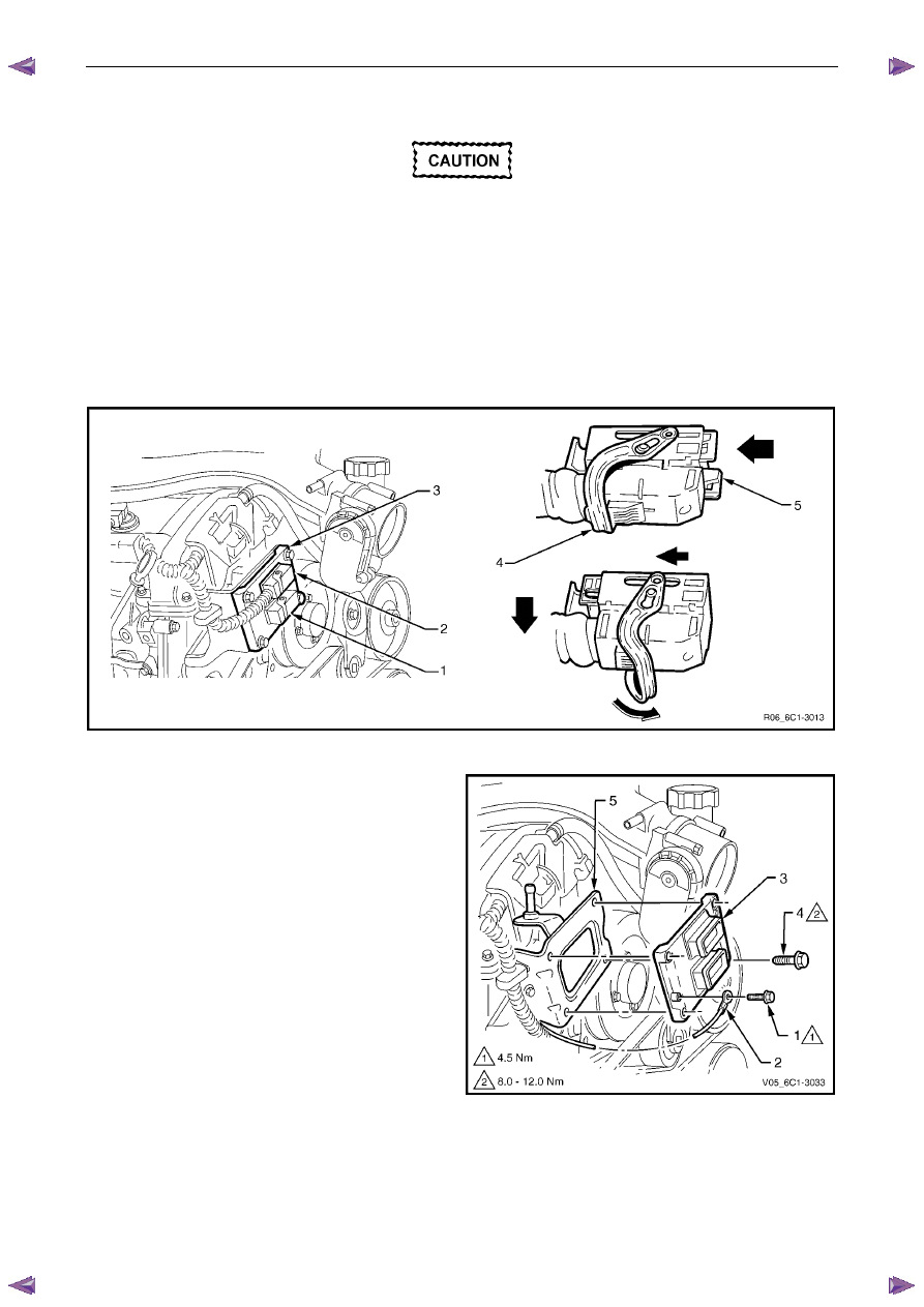
3
Disconnect the engine harness connector (1) and the front body harness connector (2) from the ECM (3). To
release each connector, lift the connector locking lever (4) whilst simultaneously pushing the connector locking
slide (5), refer to Figure 6C1-3 – 15.
Figure 6C1-3 – 15
4
Remove the screw (1) attaching the ground
terminal (2) to the ECM (3).
5
Remove the bolt (4), four places, attaching the ECM to
the mounting bracket (5) and remove the ECM.
Figure 6C1-3 – 16
Нет комментариевНе стесняйтесь поделиться с нами вашим ценным мнением.
Текст