Suzuki Grand Vitara JB627. Manual — part 233
5A-116 Automatic Transmission/Transaxle:
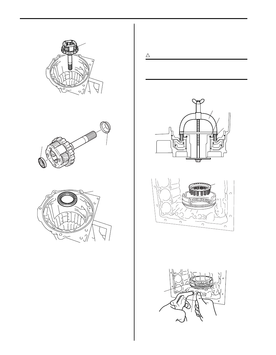
74) Remove rear planetary gear assembly (1) from
transmission case.
75) Remove thrust bearing race No.9 (1) and thrust
needle roller bearing (2) from rear planetary gear
assembly.
76) Remove thrust needle roller bearing (1) from
transmission case.
77) Compress 1st & reverse (No.4) brake return spring
(2) until the 1st & reverse (No.4) return spring is
lowered to the place 1 – 2 mm (0.039 – 0.078 in.)
from the snap ring groove by using special tool and
then remove snap ring (1).
CAUTION
!
Be careful when applying pressure, for
overpressure will cause plate section of 1st &
reverse (No.4) return spring to deform.
Special tool
(A): 09922–86010
78) Remove 1st & reverse (No.4) brake return spring (1).
79) Remove 1st & reverse (No.4) brake piston (1) by
applying compressed air (392 kPa, 4.0 kg/cm
2
, 57
psi) into oil hole (2) of transmission case.
80) Remove O-ring from 1st & reverse (No.4) brake
piston (1).
1
I4JA01512120-01
1
2
I6JB01510036-01
1
I4JA01512122-01
1
(A)
2
I4JA01512123-01
1
I4JA01512124-01
1
2
I4JA01512125-01
Automatic Transmission/Transaxle: 5A-117
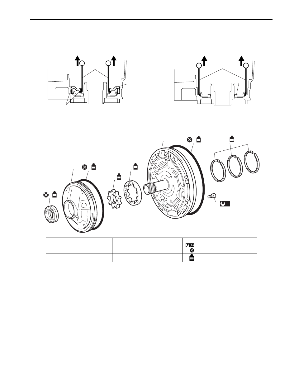
81) Remove brake reaction sleeve (1) by using special
tools.
Special tool
(A): 09920–20310
82) Remove 1st & reverse brake inner piston (1) by
using special tools.
Special tool
(A): 09920–20310
Oil Pump Assembly Components
S6JB0B5106032
1
(A)
2
I4JA01512126-01
1
(A)
I4JA01512127-01
3
FLD
FLD
FLD
FLD
2
1
4
5
6
7
FLD
8
9
FLD
(a)
I6JB01510037-01
1. Oil pump oil seal
5. Oil pump driven gear
9. Oil pump body bolt
2. Oil pump body
6. Stator shaft assembly
: 12 N
⋅m (1.2 kgf-m, 9.0 lb-ft)
3. O-ring
7. O-ring
: Do not reuse.
4. Oil pump drive gear
8. Clutch drum oil seal ring
: Apply A/T fluid
5A-118 Automatic Transmission/Transaxle:
Oil Pump Disassembly and Assembly
S6JB0B5106033
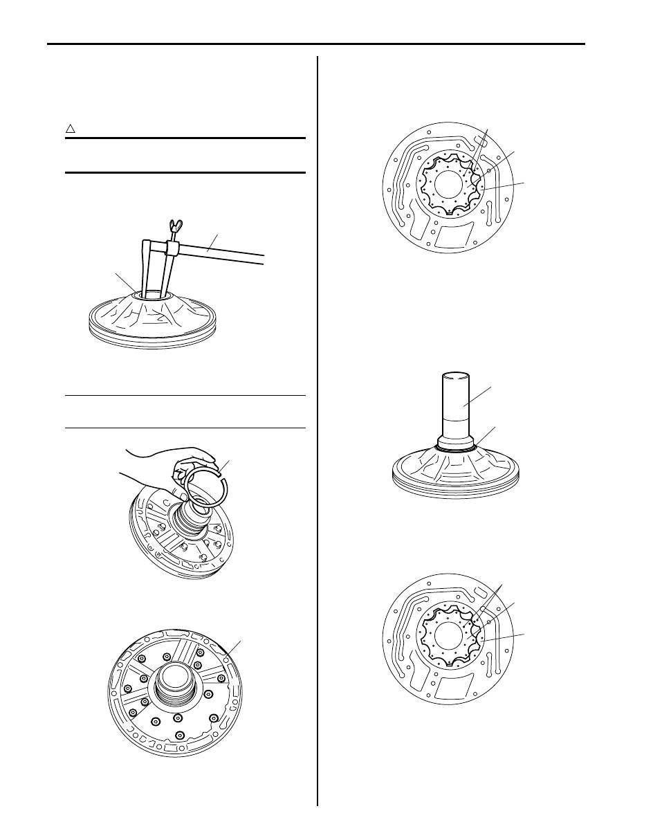
Disassembly
1) Remove oil pump oil seal (1) by using special tool.
CAUTION
!
Be careful not to damage bushing and oil
pump body.
Special tool
(A): 09913–50121
2) Remove 3 clutch drum oil seal rings (1).
NOTE
Be careful not to open seal ring more than
necessary.
3) Remove stator shaft assembly (1) from oil pump
body by removing 14 bolts.
4) Give marks (1) on drive gear (2) and driven gear (3)
by using water-proof paint.
5) Remove drive gear (2) and driven gear (3) from oil
pump body.
Assembly
1) Press-fit new oil pump oil seal (1) to oil pump body
till its end face is flush with oil pump body end face,
using special tool.
Special tool
(A): 09913–75810
2) Install drive gear (1) and driven gear (2) to oil pump
body aligning marks and facing marked surface (3)
with the direction of stator shaft assembly side.
Apply A/T fluid to gears and oil pump body.
1
(A)
I4JA01512129-01
1
I4JA01512130-01
1
I4JA01512131-01
1
2
3
I4JA01512132-01
1
(A)
I4JA01512133-01
1
3
2
I4JA01512134-01

Automatic Transmission/Transaxle: 5A-119
3) Apply A/T fluid to new O-ring (1) and then install O-
ring to oil pump body.
4) Install stator shaft assembly (1) to oil pump.
Tighten 14 bolts to specified torque.
Tightening torque
Oil pump body bolt (a): 11 N·m (1.1 kgf-m, 8.0 lb-
ft)
5) Apply A/T fluid to 3 clutch drum oil seal rings (1).
6) Squeeze ends of oil seal rings together with wrap
distance 8 mm (0.314 in.) or less and then install
them to stator shaft groove.
CAUTION
!
Do not spread seal ends excessively.
7) Check oil pump drive gear rotation as the following
procedure.
a) Place oil pump body (2) on torque converter (1).
b) Make sure drive gear rotates smoothly.
c) Remove oil pomp body (2) from torque converter
(1).
CAUTION
!
Be careful not to damage oil pump body oil
seal.
8) Apply A/T fluid to new O-ring (1) and then install O-
ring to oil pump body.
1
I4JA01512135-01
1
I4JA01512136-01
1
I4JA01512137-01
2
1
I4JA01512138-01
1
I4JA01512139-01
Нет комментариевНе стесняйтесь поделиться с нами вашим ценным мнением.
Текст