Suzuki Grand Vitara JB627. Manual — part 234
5A-120 Automatic Transmission/Transaxle:
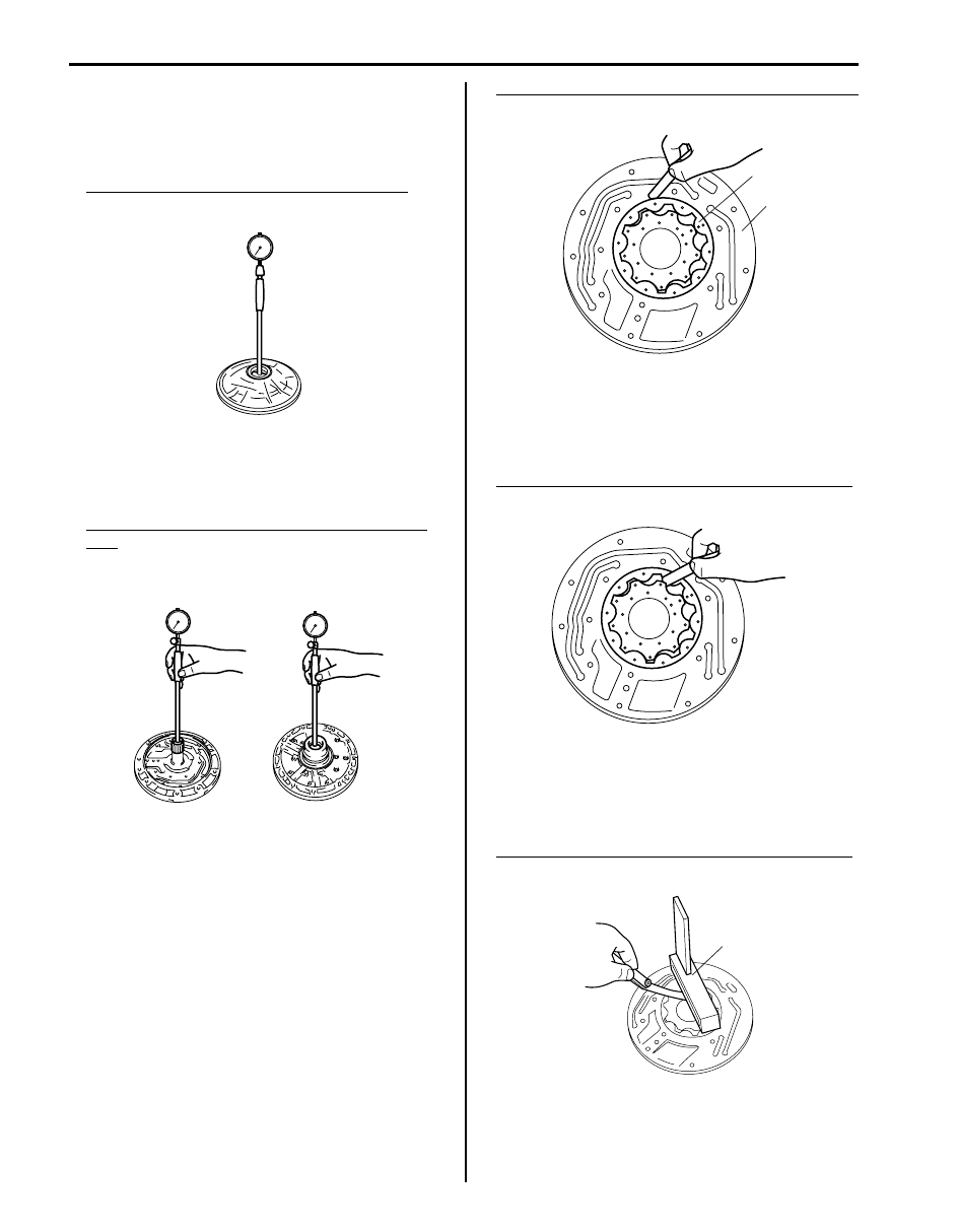
Oil Pump Inspection
S6JB0B5106034
• Measure inside diameter of oil pump body bushing.
If inside diameter exceeds limit, replace oil pump
body.
Oil pump body bushing inside diameter limit
38.188 mm (1.504 in.)
• Measure inside diameter of stator shaft assembly
bushing.
If inside diameter exceeds limit, replace stator shaft
assembly.
Stator shaft assembly bushing inside diameter
limit
Torque converter side: 21.577 mm (0.850 in.)
Output shaft side: 32.08 mm (1.263 in.)
• Check oil pump body clearance of driven gear.
Push driven gear (1) to one side of oil pump body (2).
Using a feeler gauge, measure clearance between
driven gear (1) and oil pump body (2).
If clearance exceeds standard value, replace oil pump
assembly.
Clearance between driven gear and oil pump body
Standard: 0.10 – 0.17 mm (0.004 – 0.007 in.)
• Check tip clearance of driven gear.
Measure radial clearance between driven and drive
gears tooth tip.
If clearance exceeds standard value, replace oil pump
assembly.
Tip clearance between driven gear and drive gear
Standard: 0.07 – 0.15 mm (0.003 – 0.006 in.)
• Check side clearance of both gears.
Using a straightedge (1) and a feeler gauge, measure
side clearance between gears and oil pump body.
If clearance exceeds standard value, replace oil pump
assembly.
Side clearance between gears and oil pump body
Standard: 0.02 – 0.05 mm (0.0008 – 0.002 in.)
I4JA01512140-01
I4JA01512141-01
1
2
I4JA01512142-01
I4JA01512143-01
1
I4JA01512144-01
Automatic Transmission/Transaxle: 5A-121
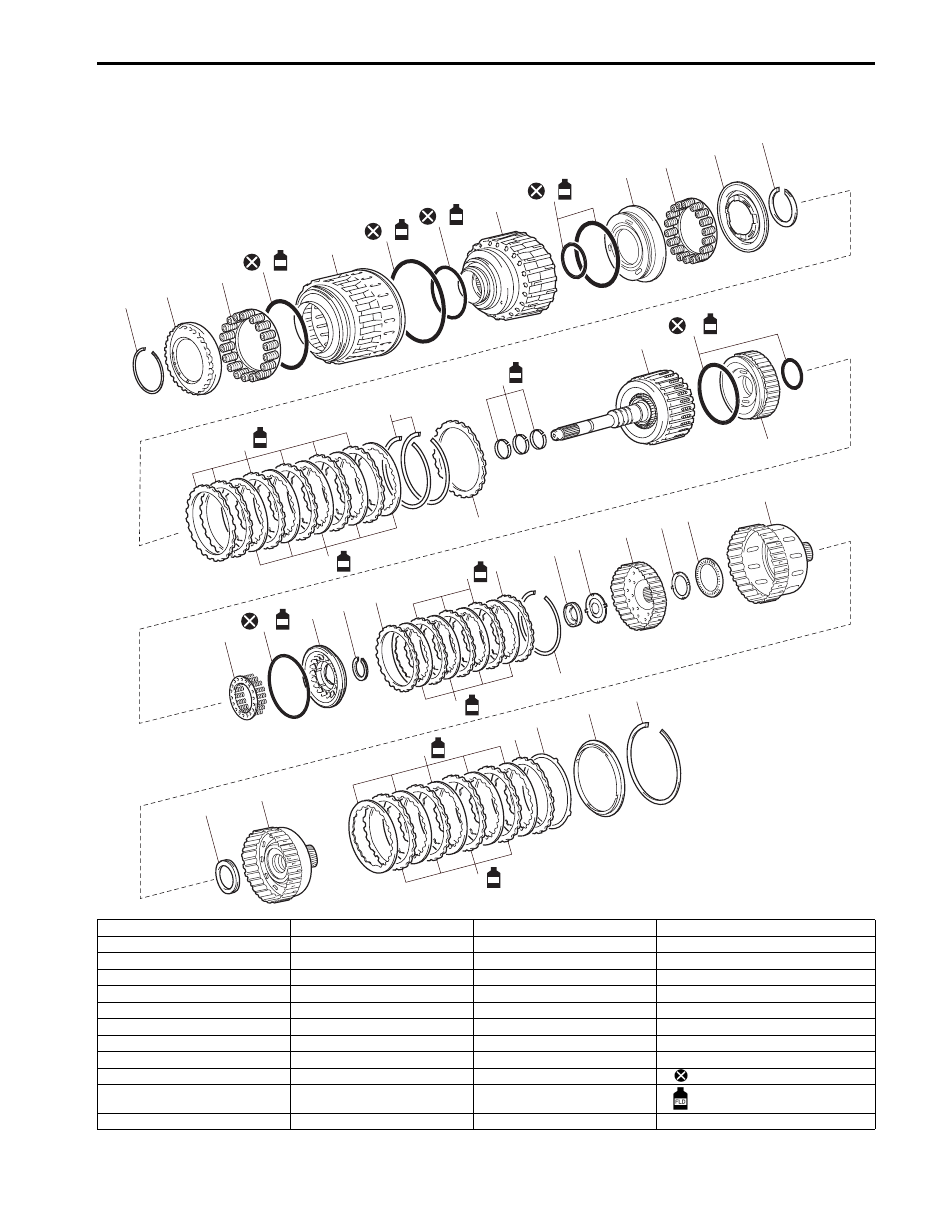
Clutch Drum & Input Shaft Assembly Components
S6JB0B5106035
1
23
38
39
25
26
27
29
30
31
32
33
34
35
36
37
28
18
17
2
3
5
8
10
20
22
11
12
13
4
FLD
7
FLD
19
FLD
24
FLD
21
FLD
6
FLD
9
FLD
FLD
FLD
15
FLD
14
FLD
42
41
FLD
43
44
45
40
FLD
I6JB01510038-02
1. Snap ring
13. Snap ring
25. Clutch balancer No.1
37. Direct clutch hub
2. Clutch balancer No.3
14. Direct clutch plate
26. Snap ring
38. Thrust needle roller bearing
3. Reverse clutch return spring
15. Direct clutch disc
27. Forward clutch flange
39. Reverse clutch hub
4. O-ring
16. Direct clutch flange
28. Forward clutch disc
40. Reverse clutch disc
5. Reverse clutch piston
17. Snap ring
29. Forward clutch plate
41. Reverse clutch plate
6. O-ring
18. Reverse clutch flange
30. Forward clutch flange
42. Reverse clutch flange
7. O-ring
19. Input shaft oil seal ring
31. Snap ring
43. Clutch cushion plate
8. Clutch drum
20. Input shaft
32. Thrust needle roller bearing
44. Reverse clutch reaction sleeve
9. O-ring
21. O-ring
33. Thrust bearing race
45. Snap ring
10. Direct clutch piston
22. Forward clutch piston
34. Forward clutch hub
: Do not reuse.
11. Direct clutch return spring
23. Forward clutch return spring
35. Thrust bearing race No.2
: Apply A/T fluid
12. Clutch balancer No.2
24. O-ring
36. Thrust needle roller bearing
5A-122 Automatic Transmission/Transaxle:
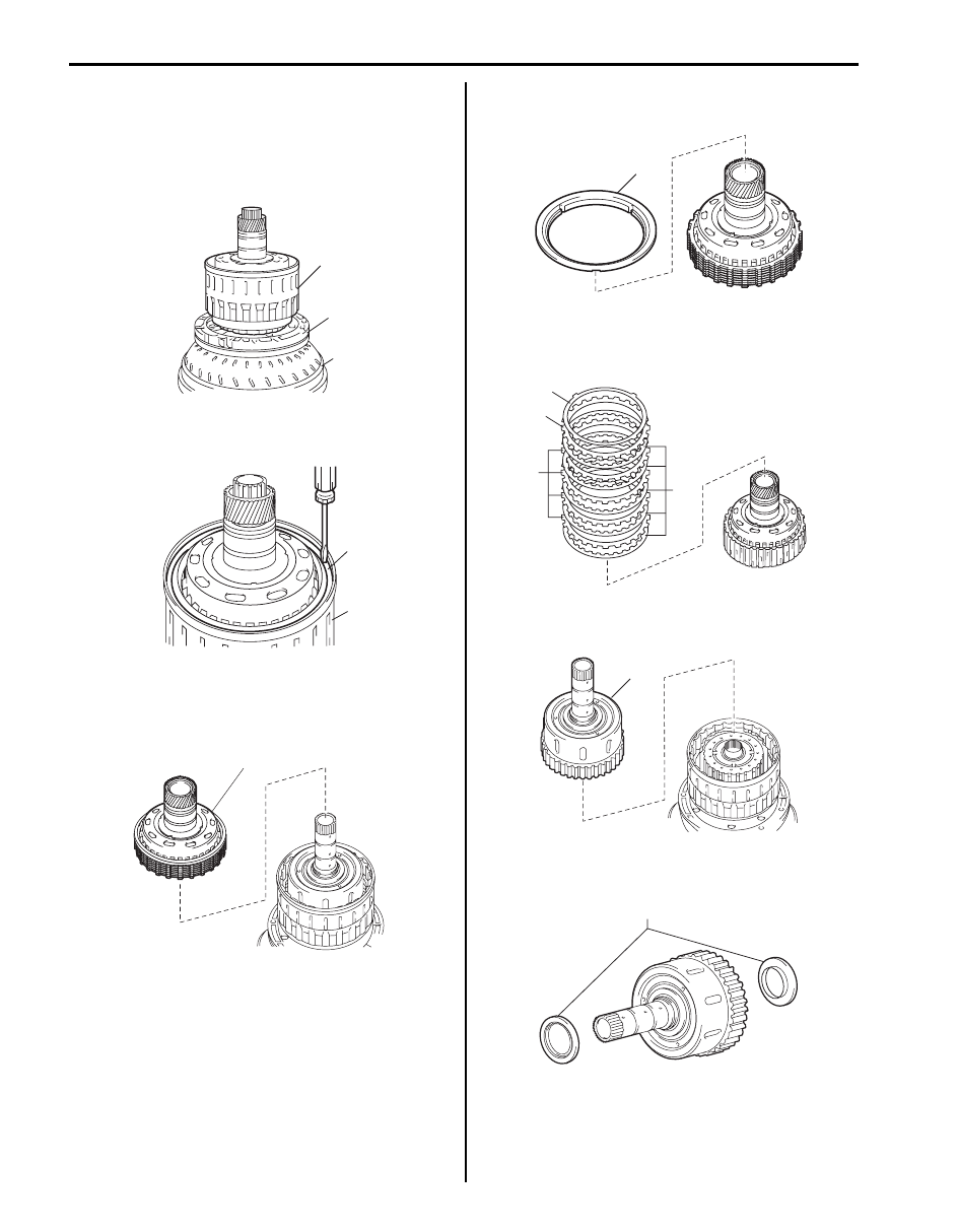
Clutch Drum & Input Shaft Assembly
Disassembly
S6JB0B5106036
1) Place oil pump (1) onto torque converter (2), and
then place clutch drum and input shaft assembly (3)
onto oil pump (1).
2) Remove snap ring (1) from clutch drum and input
shaft assembly (2) by using flat end rod or the like.
3) Remove reverse clutch hub (1) with reverse clutch
reaction sleeve, clutch cushion plate, reverse clutch
flange, 4 reverse clutch discs and 3 reverse clutch
plates from clutch drum assembly.
4) Remove reverse clutch reaction sleeve (1) from
reverse clutch hub.
5) Remove clutch cushion plate (1), reverse clutch
flange “F”, reverse clutch plates “P” and reverse
clutch discs “D” from reverse clutch hub.
6) Remove direct clutch hub (1) from clutch drum
assembly.
7) Remove 2 thrust needle roller bearings (1) from
direct clutch hub.
3
1
2
I4JA01512146-01
1
2
I4JA01512147-01
1
I4JA01512148-01
1
I4JA01512149-01
1
P
D
F
I6JB01510039-01
1
I4JA01512151-01
1
I4JA01512152-01
Automatic Transmission/Transaxle: 5A-123
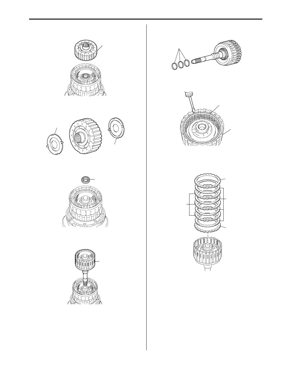
8) Remove forward clutch hub (1) from clutch drum
assembly.
9) Remove thrust bearing race No.2 (1) and thrust
bearing race (2) from forward clutch hub.
10) Remove thrust needle roller bearing (1) from clutch
drum assembly.
11) Remove input shaft assembly (1) from clutch drum
assembly.
12) Remove 3 oil seal rings (1) from input shaft
assembly.
13) Remove snap ring (1) from input shaft assembly (2)
by using flat end rod or the like.
14) Remove forward clutch flanges “F”, forward clutch
discs “D” and forward clutch plates “P” from input
shaft assembly.
1
I4JA01512153-01
1
2
I4JA01512154-01
1
I4JA01512155-01
1
I4JA01512156-01
1
I4JA01512157-01
1
2
I4JA01512158-01
F
D
P
F
I4JA01512159-01
Нет комментариевНе стесняйтесь поделиться с нами вашим ценным мнением.
Текст