Suzuki Grand Vitara JB627. Manual — part 235
5A-124 Automatic Transmission/Transaxle:
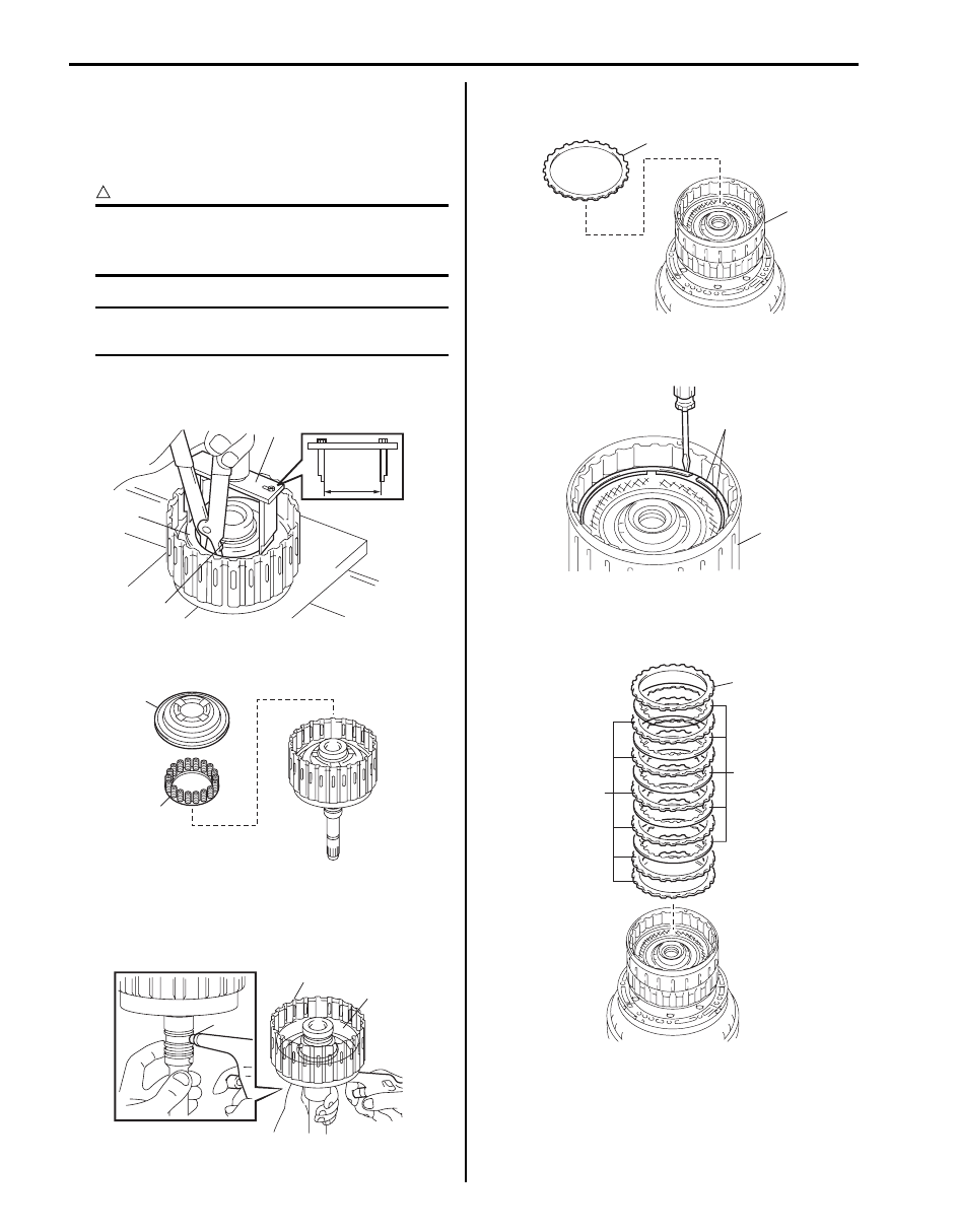
15) Compress clutch balancer No.1 and forward clutch
return spring (1) until the clutch balancer No.1 is
lowered to the place 1 – 2 mm (0.039 – 0.078 in.)
from the snap ring groove by using special tool and
hydraulic press, and then remove snap ring (2).
CAUTION
!
Be careful when applying pressure, for
overpressure will cause forward clutch return
spring to deform.
NOTE
Set special tool to the width of “a” 68 mm
(2.652 in.) as shown in figure.
Special tool
(A): 09926–96520
16) Remove clutch balancer No.1 (1) and forward clutch
return spring (2) from input shaft assembly.
17) Remove forward clutch piston (1) from input shaft
assembly (2) by applying compressed air (392 kPa,
4.0 kg/cm
2
, 57 psi) into oil hole (3) of input shaft
assembly as shown in figure.
18) Remove reverse clutch flange (1) from clutch drum
assembly (2).
19) Remove 2 snap rings (1) from clutch drum assembly
(2) by using flat end rod or the like.
20) Remove direct clutch flange “F”, direct clutch plates
“P” and direct clutch discs “D” from clutch drum
assembly.
2
(A)
“a”
1
I4JA01512160-01
1
2
I4JA01512161-01
3
2
1
I4JA01512162-01
1
2
I4JA01512163-01
1
2
I4JA01512164-01
F
P
D
I6JB01510040-01
Automatic Transmission/Transaxle: 5A-125
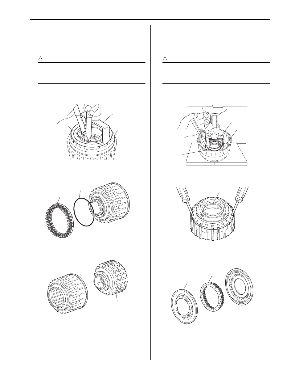
21) Compress clutch balancer No.3 and reverse clutch
return spring (1) until the clutch balancer No.3 is
lowered to the place 1 – 2 mm (0.039 – 0.078 in.)
from the snap ring groove by using special tool and
hydraulic press, and then remove snap ring (2).
CAUTION
!
Be careful when applying pressure, for
overpressure will cause reverse clutch return
spring to deform.
Special tool
(A): 09926–96040
22) Remove reverse clutch return spring (1) and O-ring
(2) from reverse clutch piston.
23) Remove reverse clutch piston sub assembly from
clutch drum sub assembly (1).
24) Compress clutch balancer No.2 and direct clutch
return spring (1) until the clutch balancer No.2 is
lowered to the place 1 – 2 mm (0.039 – 0.078 in.)
from the snap ring groove by using special tool and
hydraulic press, and then remove snap ring (2).
CAUTION
!
Be careful when applying pressure, for
overpressure will cause direct clutch return
spring to deform.
Special tool
(A): 09926–96040
25) Using 2 screw drivers, remove direct clutch piston
sub assembly (1) from clutch drum.
26) Remove clutch balancer No.2 (1) and direct clutch
return spring (2) from direct clutch piston sub
assembly.
2
1
(A)
I4JA01512166-01
1
2
I4JA01512167-01
1
I4JA01512168-01
1
(A)
2
I4JA01512169-01
1
I4JA01512170-01
1
2
I4JA01512171-01
5A-126 Automatic Transmission/Transaxle:
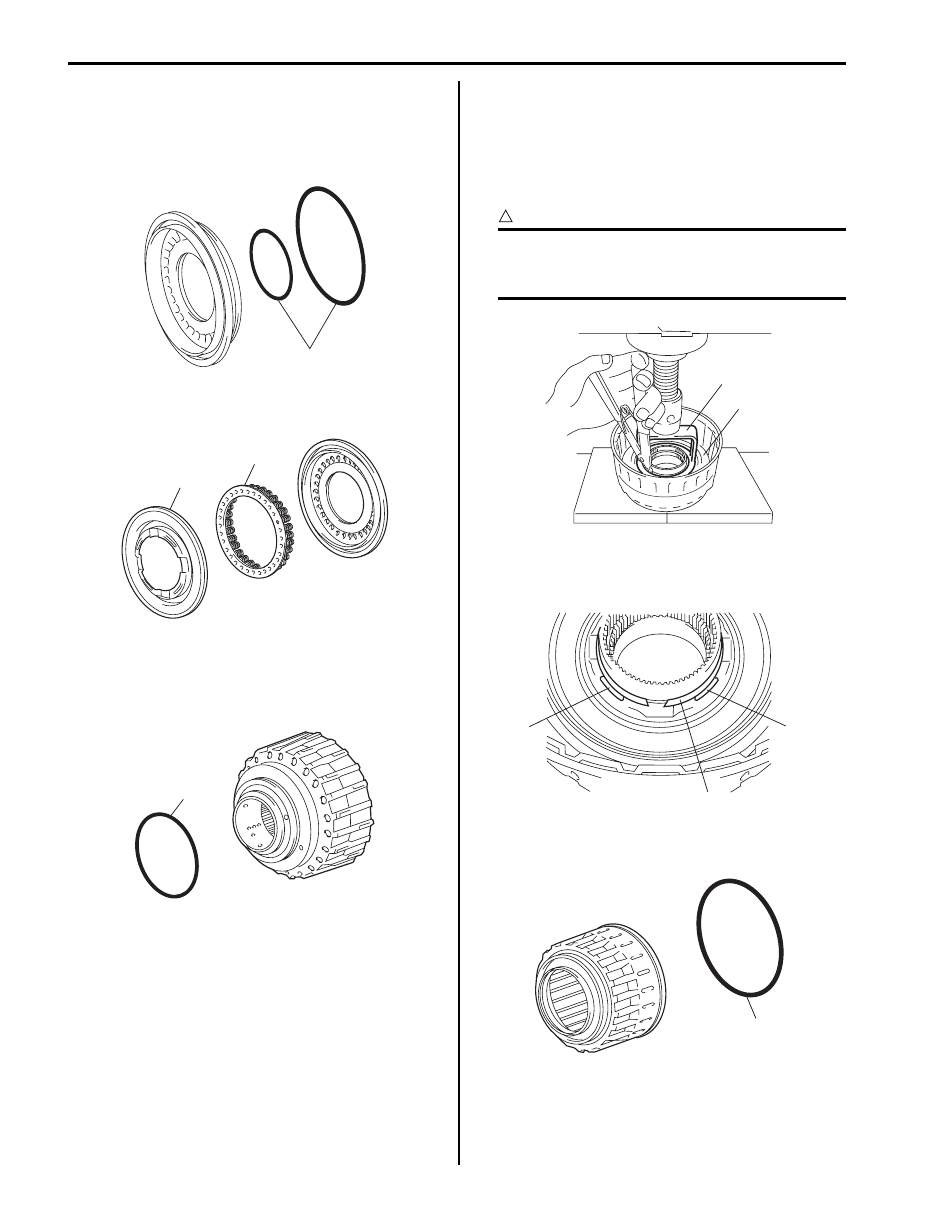
Clutch Drum & Input Shaft Assembly
Reassembly
S6JB0B5106037
1) Apply A/T fluid to new 2 O-rings (1) and then install
O-rings to direct clutch piston.
2) Install clutch balancer No.2 (1) and direct clutch
return spring (2) to direct clutch piston sub assembly.
3) Apply A/T fluid to new O-ring (1), and then install O-
ring to clutch drum sub assembly.
4) Press-fit direct clutch piston into clutch drum by
hands.
5) Compress clutch balancer No.2 (1) until the clutch
balancer No.2 is lowered to the place 1 – 2 mm
(0.039 – 0.078 in.) from the snap ring groove by
using special tool and hydraulic press.
Special tool
(A): 09926–96040
CAUTION
!
Be careful when applying pressure, for
overpressure will cause direct clutch return
spring to deform.
6) Install snap ring (1) as set snap ring end gap
between snap ring stoppers (2) of clutch balancer
No.2.
7) Apply A/T fluid to new O-ring (1), and then install O-
ring to reverse clutch piston sub assembly.
1
I4JA01512172-01
1
2
I4JA01512173-01
1
I4JA01512174-01
1
(A)
I4JA01512175-01
2
2
1
I4JA01512176-01
1
I4JA01512177-01
Automatic Transmission/Transaxle: 5A-127
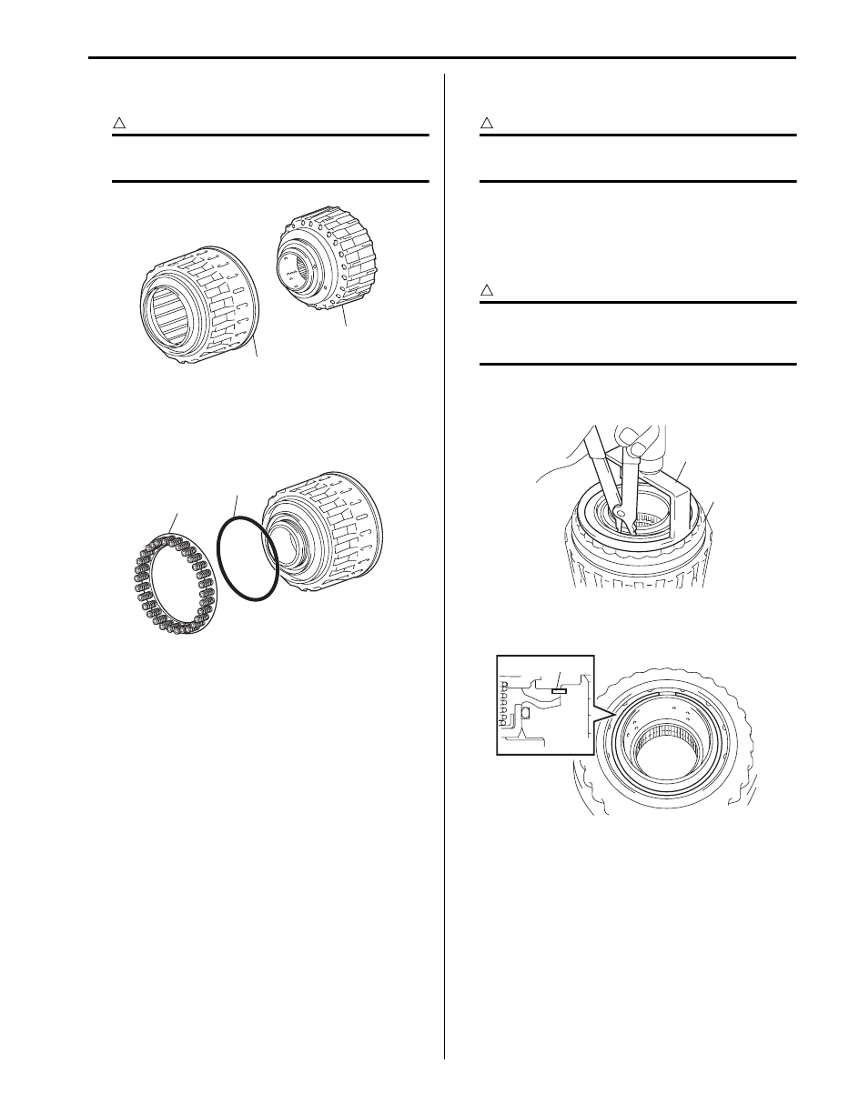
8) Press-fit clutch drum sub assembly (1) into reverse
clutch piston (2) by hands.
CAUTION
!
Do not twist or deviate O-rings during
installation.
9) Apply A/T fluid to new O-ring (1), and then install O-
ring to reverse clutch piston sub assembly.
10) Install reverse clutch return spring (2) onto reverse
clutch piston sub assembly.
11) Place clutch balancer No.3 (1) onto reverse clutch
piston sub assembly.
CAUTION
!
Do not twist or deviate O-ring during
installation.
12) Compress clutch balancer No.3 (1) until the clutch
balancer No.3 is lowered to the place 1 – 2 mm
(0.039 – 0.078 in.) from the snap ring groove by
using special tool and hydraulic press, and then
install snap ring.
CAUTION
!
Be careful when applying pressure, for
overpressure will cause reverse clutch return
spring to deform.
Special tool
(A): 09926–96040
13) Set end gap of snap ring (1) in piston as shown in
figure.
1
2
I4JA01512178-01
2
1
I4JA01512179-01
1
(A)
I4JA01512180-01
1
I4JA01512181-01
Нет комментариевНе стесняйтесь поделиться с нами вашим ценным мнением.
Текст