Suzuki Grand Vitara JB627. Manual — part 236
5A-128 Automatic Transmission/Transaxle:
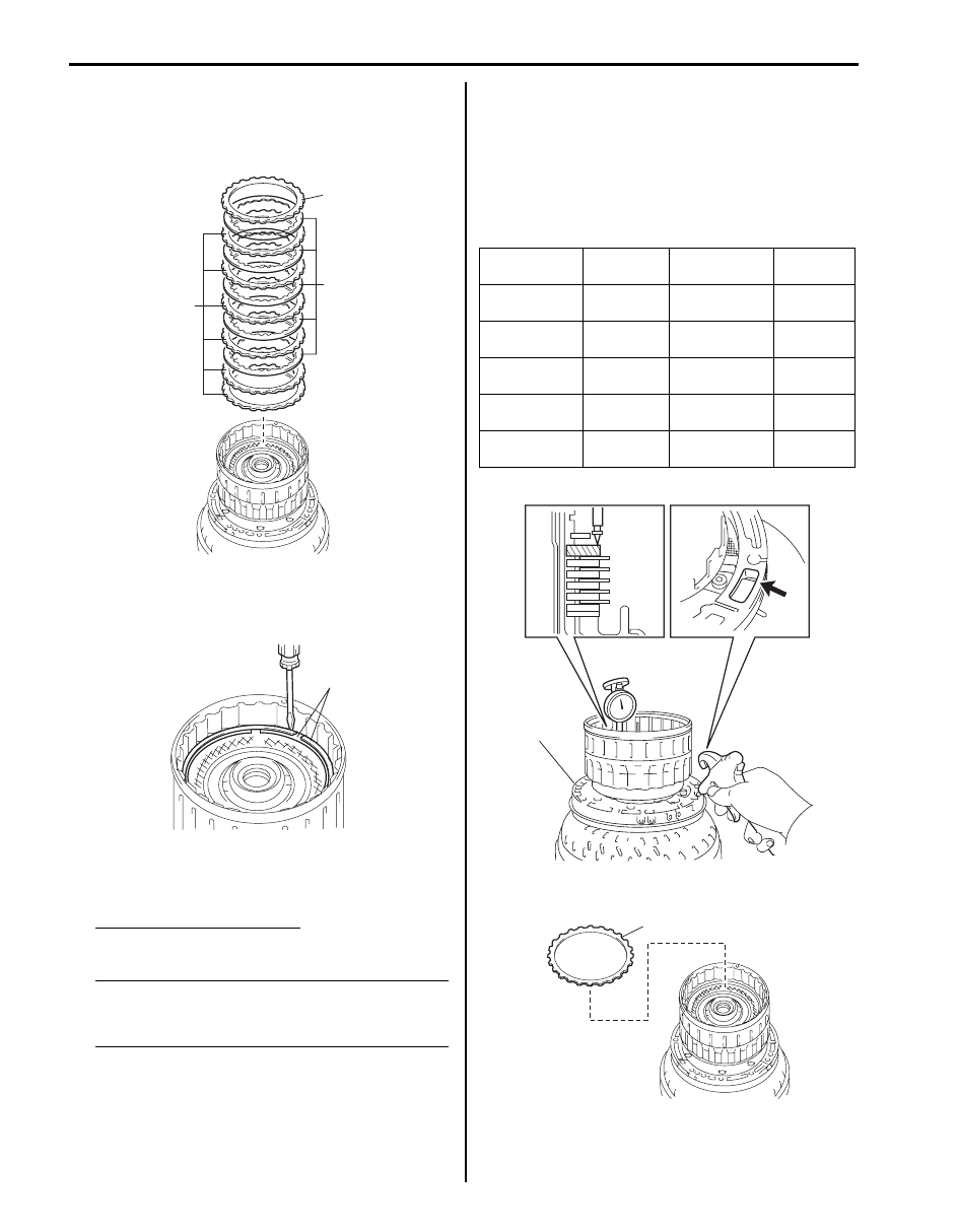
14) Install direct clutch plates “P” and direct clutch discs
“D” in the following order.
P - P - D - P - D - P - D - P - D - P - D
15) Install direct clutch flange “F”.
16) Install 2 snap rings (1) by using flat end rod or the
like being sure not to align snap rings end gap with
cut portion of clutch drum sub assembly.
17) Measure pack clearance of direct clutch by applying
compressed air (392 kPa, 4.0 kg/cm
2
, 57 psi) into oil
hole (1) of oil pump (2) as shown in figure.
Direct clutch pack clearance
0.50 – 0.80 mm (0.020 – 0.031 in.)
NOTE
Install a selective flange (t 3.4 mm) when
measuring the moving distance. (shaded
area in figure.)
• Flange moving distance A: 0.36 – 1.242 mm
(0.0141 – 0.0489 in.)
Piston stroke: Flange moving distance A – 0.15
mm (0.0059 in.)
If the pack clearance is out of specification, select
another flange with suitable thickness from the list
below and replace it.
Available direct clutch flange thickness
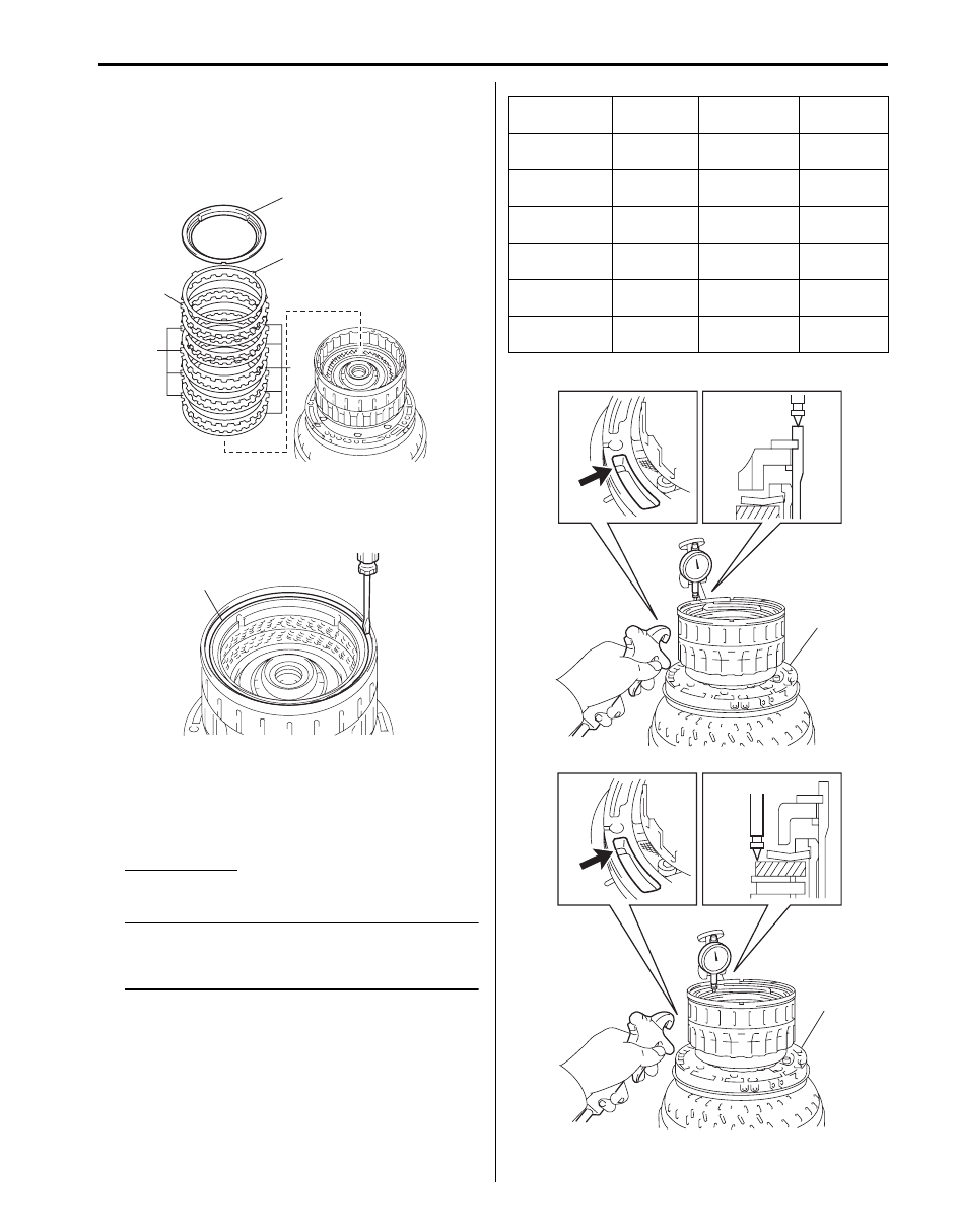
18) Install reverse clutch flange (1).
F
P
D
I6JB01510040-01
1
I4JA01512183-01
Identification
No.
Thickness
Identification
No.
Thickness
0
3.0 mm
(0.118 in.)
5
3.5 mm
(0.138 in.)
1
3.1 mm
(0.122 in.)
6
3.6 mm
(0.142 in.)
2
3.2 mm
(0.126 in.)
7
3.7 mm
(0.146 in.)
3
3.3 mm
(0.130 in.)
8
3.8 mm
(0.150 in.)
4
3.4 mm
(0.134 in.)
—
—
A
1
2
I4JA01512184-01
1
I4JA01512185-01
Automatic Transmission/Transaxle: 5A-129
19) Install reverse clutch reaction sleeve (1), clutch
cushion plate (2), reverse clutch flange “F”, reverse
clutch discs “D” and reverse clutch plates “P” in the
following order.
D - P - D - P - D - P - D - P - D - F
20) Install snap ring (1) by using flat end rod or the like
being sure not to align snap ring end gap with cut
portion of clutch drum sub assembly.
21) Measure reverse clutch piston stroke (A) and the
moving distance (B) of reverse clutch flange at the
both end across a diameter by applying compressed
air (392 kPa, 4 kg/cm
2
, 57 psi) into oil hole (1) of oil
pump (2) as shown in figure.
Pack Clearance
0.5 – 0.8 mm (0.020 – 0.031 in.)
NOTE
Install selective flange (t 3.3 mm) when
measuring the moving distance. (shaded
area in figure)
• Piston stroke A: 1.69 – 2.81 mm (0.0665 – 0.11
in.)
Flange moving distance B: 1.20 – 1.68 mm
(0.0472 – 0.0661 in.)
Pack clearance: Piston stroke A – Flange moving
distance B – 0.16 mm (0.0063 in.)
If the pack clearance is out of specification, select
another flange with suitable thickness from the list
below and replace it.
Available reverse clutch flange thickness
1
P
D
F
2
I6JB01510041-01
1
I4JA01512187-01
Identification
No.
Thickness
Identification
No.
Thickness
0
2.8 mm
(0.110 in.)
6
3.4 mm
(0.134 in.)
1
2.9 mm
(0.114 in.)
7
3.5 mm
(0.138 in.)
2
3.0 mm
(0.118 in.)
8
3.6 mm
(0.142 in.)
3
3.1 mm
(0.122 in.)
9
3.7 mm
(0.146 in.)
4
3.2 mm
(0.126 in.)
A
3.8 mm
(0.150 in.)
5
3.3 mm
(0.130 in.)
—
—
B
1
2
A
1
2
I4JA01512188-01
5A-130 Automatic Transmission/Transaxle:
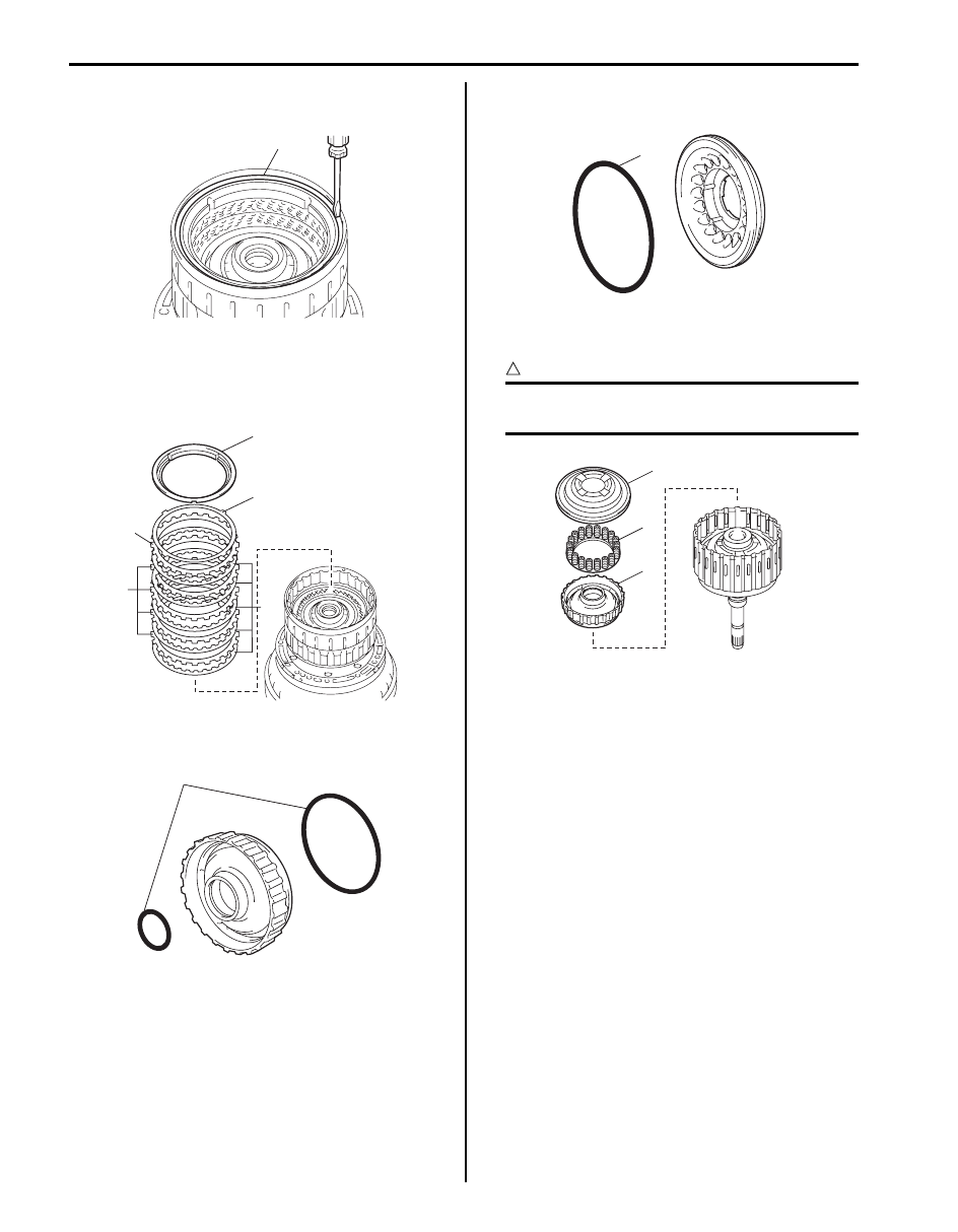
22) Remove snap ring (1) from clutch drum sub
assembly by using flat end rod or the like.
23) Remove reverse clutch reaction sleeve (1), clutch
cushion plate (2), reverse clutch flange “F”, reverse
clutch discs “D” and clutch plates “P” from clutch
drum sub assembly.
24) Apply A/T fluid to new 2 O-rings (1) and then install
O-rings to forward clutch piston.
25) Apply A/T fluid to new O-ring (1), and then install O-
ring to clutch balancer No.1.
26) Install forward clutch piston (1), clutch balancer No.1
(3) and forward clutch return spring (2).
CAUTION
!
Do not twist or deviate O-rings during
installation.
1
I4JA01512189-01
1
P
D
F
2
I6JB01510041-01
1
I4JA01512191-01
1
I4JA01512192-01
3
2
1
I4JA01512193-01
Automatic Transmission/Transaxle: 5A-131
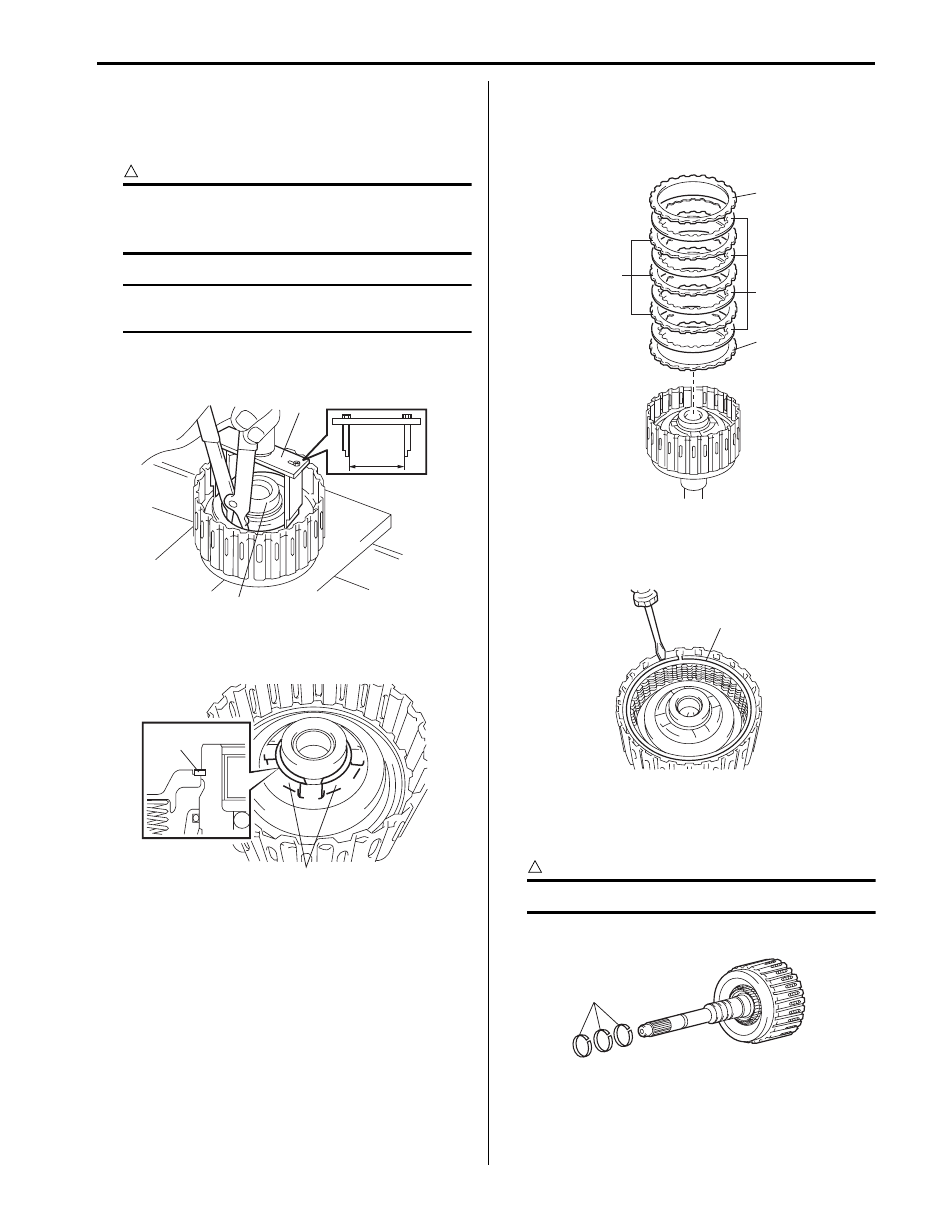
27) Compress clutch balancer No.1 (1) until the clutch
balancer No.1 is lowered to the place 1 – 2 mm
(0.039 – 0.078 in.) from the snap ring groove by
using special tool and hydraulic press.
CAUTION
!
Be careful when applying pressure, for
overpressure will cause forward clutch return
spring to deform.
NOTE
Set special tool to the width of “a” 68 mm
(2.652 in.) as shown in figure.
Special tool
(A): 09926–96520
28) Install snap ring as set snap ring end gap between
snap ring stoppers (2) of clutch balancer No.1.
29) Install forward clutch flange “F”.
30) Install clutch plates “P”, forward clutch flange “F” and
clutch discs “D” in the following order.
D - P - D - P - D - P - D - F
31) Install snap ring (1) by using flat end rod or the like
being sure not to align snap ring end gap with cut
portion of input shaft assembly.
32) Apply A/T fluid to 3 oil seal rings (1).
33) Squeeze the ends of 3 oil seal rings (1) together, and
then install oil seal rings to input shaft groove.
CAUTION
!
Do not spread seal excessively.
34) Check seals rotate smoothly.
1
(A)
“a”
I4JA01512194-01
1
2
I4JA01512195-01
F
D
P
F
I4JA01512196-01
1
I4JA01512197-01
1
I4JA01512198-01
Нет комментариевНе стесняйтесь поделиться с нами вашим ценным мнением.
Текст