Suzuki Grand Vitara JB627. Manual — part 238
5A-136 Automatic Transmission/Transaxle:
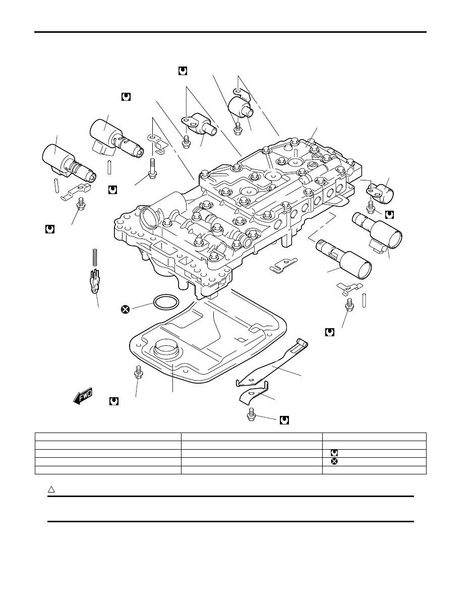
Valve Body Assembly Components
S6JB0B5106039
CAUTION
!
When replacing pressure control solenoid valve-A, -B, -C and TCC solenoid valve, it is strictly required
to replace it together with valve body assembly as a set.
1
2
3
4
5
6
7
8
9
10
11
12
11 N·m (1.1 kg-m)
11 N·m (1.1 kg-m)
11 N·m (1.1 kg-m)
11 N·m (1.1 kg-m)
11 N·m
(1.1 kg-m)
11 N·m (1.1 kg-m)
11 N·m (1.1 kg-m)
10 N·m (1.0 kg-m)
I4JA01512353-01
1. Valve body assembly
6. Shift solenoid valve-E
11. Oil strainer
2. Pressure control solenoid valve-A
7. Pressure control solenoid valve-C
12. Check ball body
3. Pressure control solenoid valve-B
8. TCC solenoid
: Tightening torque
4. Shift solenoid valve-A
9. Manual shift lever spring
: Do not reuse.
5. Shift solenoid valve-B
10. Spring plate
Automatic Transmission/Transaxle: 5A-137
Automatic Transmission Unit Assembly
S6JB0B5106040
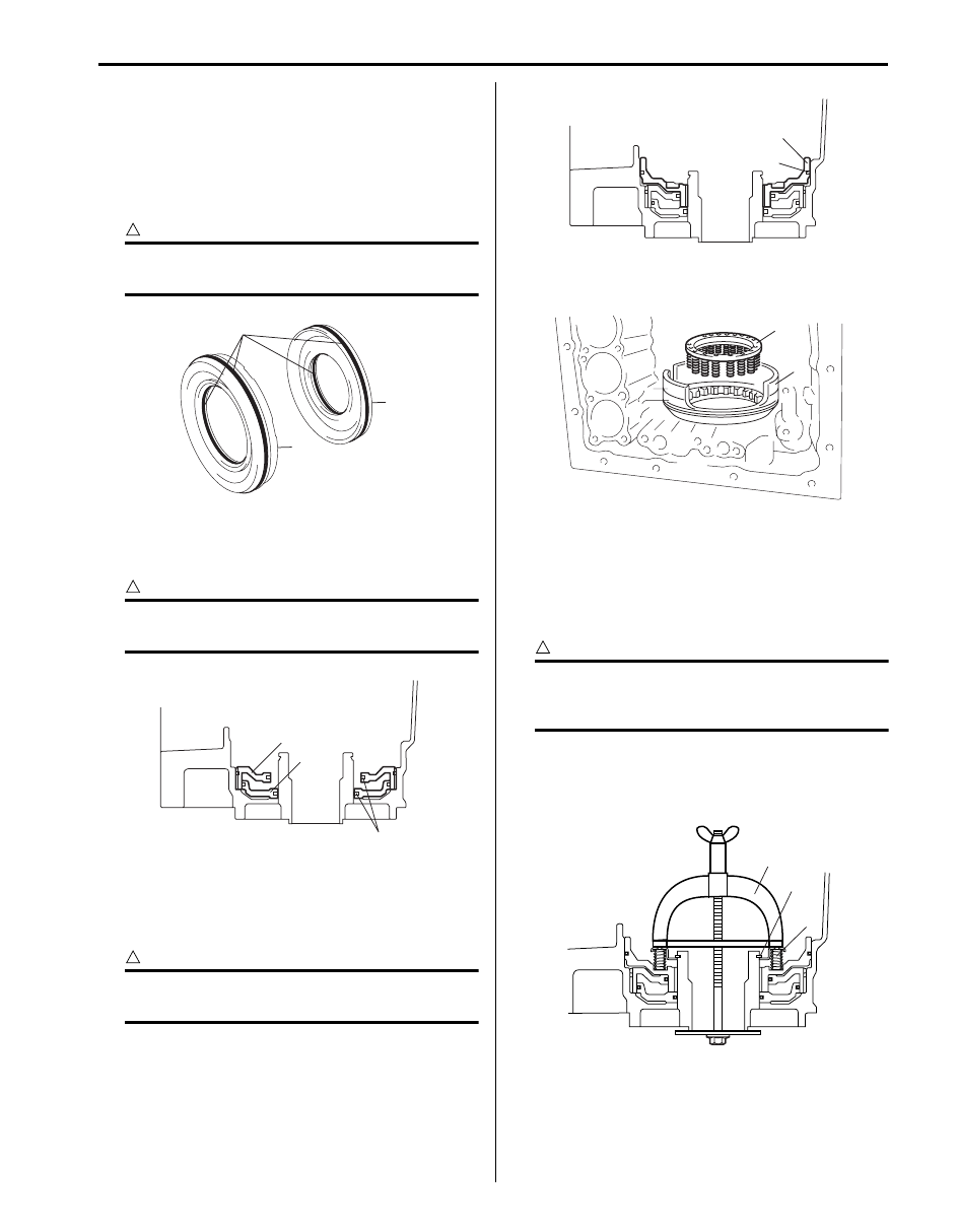
1) After applying A/T fluid to new 4 O-rings (1) and then
install O-rings to 1st & reverse (No.4) brake inner
piston (2) and brake reaction sleeve (3).
2) Install 1st & reverse (No.4) brake inner piston (2) to
brake reaction sleeve (3).
CAUTION
!
Do not twist or deviate O-rings (1) during
installation.
3) Install 1st & reverse (No.4) brake inner piston (1)
including brake reaction sleeve (2) to transmission
case.
CAUTION
!
Do not twist or deviate O-rings (3) during
installation.
4) After applying A/T fluid to new O-ring (1) and then
install O-ring to 1st & reverse (No.4) brake piston (2).
5) Install 1st & reverse (No.4) brake piston (2) to
transmission case.
CAUTION
!
Do not twist or deviate O-ring (1) during
installation.
6) Place 1st & reverse (No.4) brake return spring (1) on
1st & reverse (No.4) brake piston (2).
7) Place snap ring (1) on 1st & reverse (No.4) brake
return spring and compress 1st & reverse (No.4)
brake return spring (2) until the 1st & reverse (No.4)
brake return spring is lowered to the place 1 – 2 mm
(0.039 – 0.078 in.) from the snap ring groove by
using special tool.
CAUTION
!
Be careful when applying pressure, for
overpressure will cause plate section of 1st &
reverse (No.4) brake return spring to deform.
Special tool
(A): 09922–86010
8) Install snap ring (1).
1
2
3
I4JA01512216-01
1
2
3
I4JA01512217-01
1
2
I4JA01512218-01
1
2
I4JA01512219-01
1
(A)
2
I4JA01512220-01
5A-138 Automatic Transmission/Transaxle:
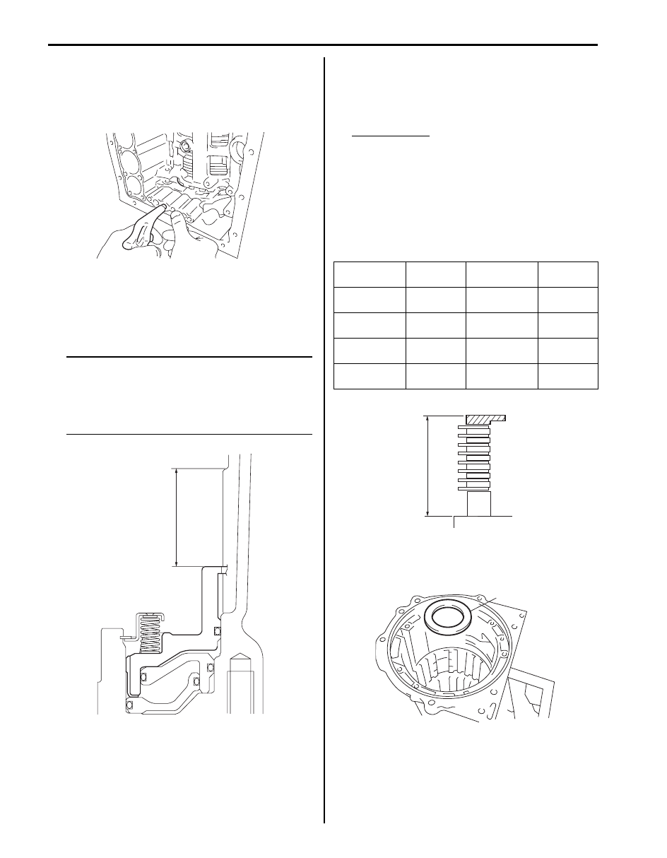
9) Make sure 1st & reverse (No.4) brake piston and 1st
& reverse (No.4) brake inner piston move smoothly
when applying low pressure compressed air (392
kPa, 4.0 kg/cm
2
, 57 psi) into oil hole of transmission
case.
10) Using vernier calipers, measure the level difference
(length A) between the upper surface of the 1st &
reverse (No.4) brake piston and the hitting surface of
1st & reverse (No.4) brake flange at the both end
across a diameter, and calculate the average.
NOTE
• 1st & reverse (No.4) brake piston must be
installed tightly to the end face of
transmission case.
• Length A:
32.68 – 33.42 mm (1.287 – 1.316 in.)
11) Using vernier calipers, measure the thickness
(length B) of the 1st & reverse (No.4) brake flanges,
the 1st & reverse (No.4) brake plates and the 1st &
reverse (No.4) brake discs altogether at the both end
across a diameter, and calculate the average.
Pack Clearance
0.7 – 1.0 mm (0.028 – 0.039 in.)
• Pack Clearance: Length A – Length B + 1.36 mm
(0.0535 in.)
Length B: 30.59 – 31.62 mm (1.204 – 1.244 in.)
12) If the pack clearance is out of specification, select
another flange with suitable thickness from the list
below and replace it.
Available 1st & reverse (No.4) brake flange thickness
13) After applying A/T fluid to thrust needle roller bearing
(1), install thrust bearing race No.9 (1) to
transmission case.
I4JA01512221-01
A
I4JA01512222-01
Identification
No.
Thickness
Identification
No.
Thickness
0
0 mm
(0 in.)
8
0.8 mm
(0.032 in.)
2
0.2 mm
(0.008 in.)
10
1.0 mm
(0.039 in.)
4
0.4 mm
(0.016 in.)
12
1.2 mm
(0.047 in.)
6
0.6 mm
(0.024 in.)
14
1.4 mm
(0.055 in.)
B
I4JA01512223-01
1
I6JB01510048-01

Automatic Transmission/Transaxle: 5A-139
14) After applying A/T fluid to thrust needle roller bearing
(2) and thrust needle roller bearing (1) and then
install thrust needle roller bearing (2) and thrust
bearing race No.9 (1) to rear planetary ring gear.
15) Install rear planetary gear assembly (1).
16) Place rear planetary flange (1) on rear planetary ring
gear (2).
17) Install snap ring (1) by using flat end rod or the like.
18) Install thrust bearing race No.8 (1), thrust needle
roller bearing (2), thrust bearing race No.7 (3) and
planetary ring gear flange assembly (4) to
intermediate shaft.
19) Install intermediate shaft (1) including planetary ring
gear flange assembly (2) to transmission case.
20) Install 1st & reverse (No.4) brake flange “F”, 1st &
reverse (No.4) brake discs “D” and 1st & reverse
(No.4) brake plates “P” in the following order.
F - D - P - D - P - D - P - D - P - D - P - D - P - D
21) Install 1st & reverse (No.4) brake flange (1) with flat
side of flange facing to toward the upside.
1
2
I6JB01510036-01
1
I4JA01512226-01
1
2
I4JA01512227-01
1
I4JA01512228-01
3
1
2
4
I4JA01512229-01
1
2
I4JA01512230-01
F
D
P
1
I4JA01512231-01
Нет комментариевНе стесняйтесь поделиться с нами вашим ценным мнением.
Текст