Suzuki: Engine K6A-YH6. Manual — part 16

7-18
REPAIR
7
Installation
Figure 7-44
1.
Clean cam cover and cylinder head gasket surfaces.
2.
Install new gasket (1) to cam cover (2).
Figure 7-45
3.
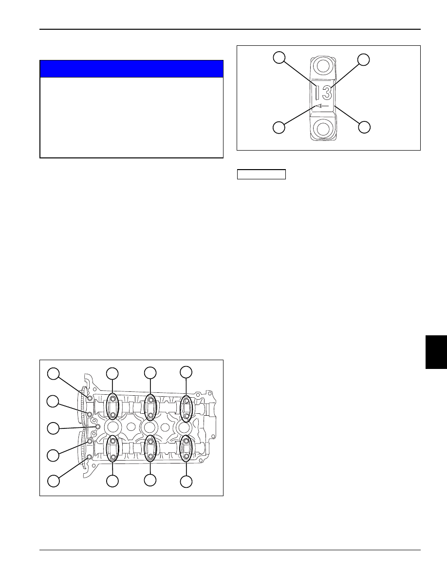
Apply Three Bond™ 1215 to locations (3, 4, 5, and 6)
as shown.
4.
Install cam cover and cap screws. (See “Cam Cover
Torque Sequence” on page 7-18.)
Cam Cover Torque Sequence
Figure 7-46
1.
Tighten cap screws (1 through 6) in sequential order
as shown. Torque cam cover cap screws at
increments of 32 lb-in. (3.6 N•m), until specification is
reached.
Cam Cover Cap Screws Torque: 96 lb-in. (11 N•m)
2.
Install PCV valve. (See “PCV Valve” on page 7-4.)
3.
Install spark plugs. (See “Spark Plugs” on page 7-8.)
4.
Install ignition coils. (See “Ignition Coils” on
page 7-8.)
Required Materials
Three Bond™ 1215 (Suzuki PN 99000-1080-15A) or
equivalent
TN0725
1
2
TN0366
3
6
4
5
TN0554
3
4
5
6
1
2
REPAIR
7-19
7
Camshafts
NOTICE
Removal
1.
Remove ignition coils. (See “Ignition Coils” on
page 7-8.)
2.
Remove spark plugs. (See “Spark Plugs” on
page 7-8.)
3.
Remove PCV valve. (See “PCV Valve” on page 7-4.)
4.
Remove cam cover. (See “Cam Cover” on
page 7-17.)
5.
Remove crankshaft pulley. (See “Crankshaft Pulley”
on page 7-37.)
6.
Remove idler pulley. (See “Idler Pulley” on
page 7-38.)
7.
Remove oil pan. (See “Oil Pan” on page 7-30.)
8.
Remove front cover. (See “Front Cover” on
page 7-12.)
9.
Remove timing chain. (See “Timing Chain” on
page 7-14.)
Figure 7-47
Figure 7-48
IMPORTANT
Mark the camshaft timing gear faces to easily
distinguish between intake and exhaust.
Take note of camshaft housings, location and
orientation to aid in assembly.
10. Loosen the camshaft housing bolts in sequence as
shown in figure 7-47.
11. Remove camshaft housings (14). Note the locations
and orientation using the stamped markings.
• The “I” or “E” markings (12) refer to intake or exhaust
side camshaft.
• The numerical markings (13) refer to the cylinder the
housing corresponds with. The cylinders are
numbered 1—3, starting from the timing chain
moving toward the rear of engine.
• The arrow marking (15) points toward the timing
chain (front of engine).
12. Remove the intake and exhaust camshafts. Inspect
camshafts for signs of wear or damage. Replace as
needed.
Remove camshaft housing cap screws using
illustrated sequence. Incorrect removal can result
in damaged camshafts.
When removing camshaft housings, camshafts,
shims, and tappets, be sure to note location and
orientation of all parts to aid in assembly.
Failure to install parts properly can result in
engine damage and failure.
TN0409
1
2
3
4
5
6
7
8
9
10
11
TN0416
13
14
15
12

7-20
REPAIR
7
Inspection
See Figures 7-49 through 7-52.
IMPORTANT
Tappets and shims must be removed before
measuring camshaft bearing clearance.
Be sure to note location and shim thickness of each
tappet.
Figure 7-49
1.
Remove twelve tappets with shims. Be sure to note
location and shim thickness of each tappet.
2.
Clean the camshaft journals and housings free of all
oil.
3.
Tear off a piece of Plastigage as long as the full
bearing width. (Tear through both the envelope and
plastic thread at the same time.) Lay the piece of
Plastigage across the full width of the lower bearing
shell about 1/4 in. (6.3 mm) off center.
Figure 7-50
IMPORTANT
Do not turn camshaft during oil clearance
measurement process.
Be sure dowel pins are properly aligned before
installing camshaft housings.
4.
Install the camshaft housings. Apply engine oil to cap
screws and tighten using sequence (1 through 11) at
increments of 32 lb-in. (3.6 N•m) until specification is
reached. Do not turn camshaft during measurement
process.
Cam Housing Cap Screw Torque: 97 lb-in. (11 N•m)
Figure 7-51
5.
Remove cap screws and camshaft housings in
opposite sequence of installation. The flattened
Plastigage (12) will adhere to either the bearing shell
or the camshaft.
6.
Using the supplied scale (13), take the measurement
at the widest point of gauging plastic.
Camshaft Oil Clearance Standard: 0.002—0.003 in.
(0.045—0.087 mm)
Camshaft Oil Clearance Limit: 0.004 in. (0.10 mm)
Required Tools and Materials
Plastigage™ Clearance Indicator
Micrometer
Inside Bore Gauge
TN0414
TN0409
11
10
9
8
7
6
5
4
3
2
1
TN0410
12
13
REPAIR
7-21
7
Figure 7-52
7.
If the oil clearance exceeds the limit, remove the
camshaft and retighten the camshaft housing to
specification.
Cam Housing Cap Screw Torque: 97 lb-in. (11 N•m)
8.
Using a micrometer and bore gauge, measure the
camshaft journal outside diameter (14) and the
journal bore diameter (15).
If the measurement is beyond the standard range,
either the camshaft or cylinder head must be
replaced.
Camshaft Journal Outside Diameter: 0.903—0.904
in. (22.934—22.955 mm)
Camshaft Journal Inside Diameter: 0.905—0.906 in.
(23.000—23.021 mm)
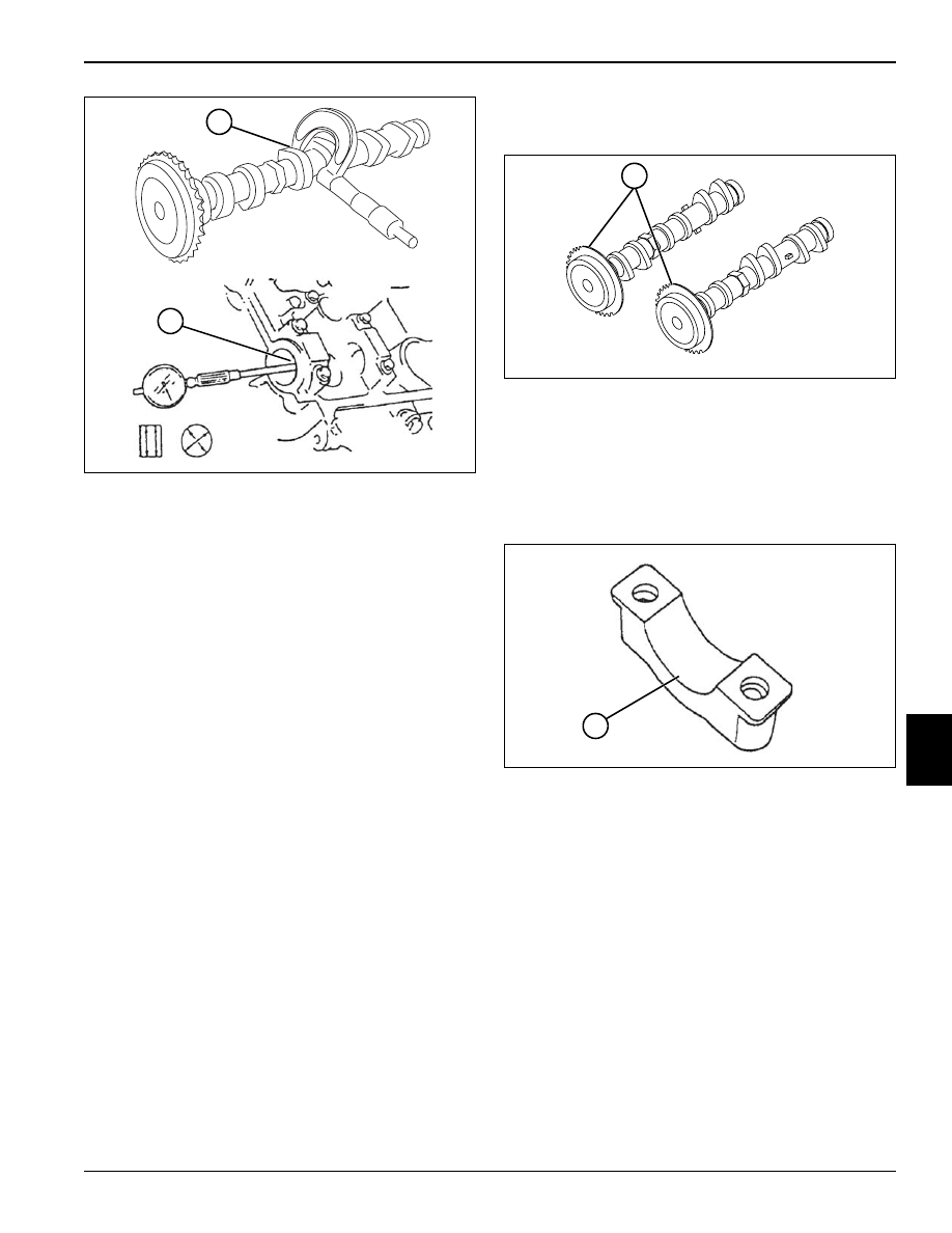
Cam Timing Sprocket
Figure 7-53
Inspect the camshaft timing sprockets (1) for wear and
damage. If any abnormal condition is noted, replace the
sprocket.
Camshaft Housing Bearing Face
Figure 7-54
Inspect the camshaft housing bearing face for pitting,
melting, and seizure. If any abnormal condition is found,
replace the cylinder head.
TN0411
14
15
TN0505
1
TN0408
1
Нет комментариевНе стесняйтесь поделиться с нами вашим ценным мнением.
Текст