Suzuki: Engine K6A-YH6. Manual — part 15
7-14
REPAIR
7
Tension Adjuster
Removal and Installation
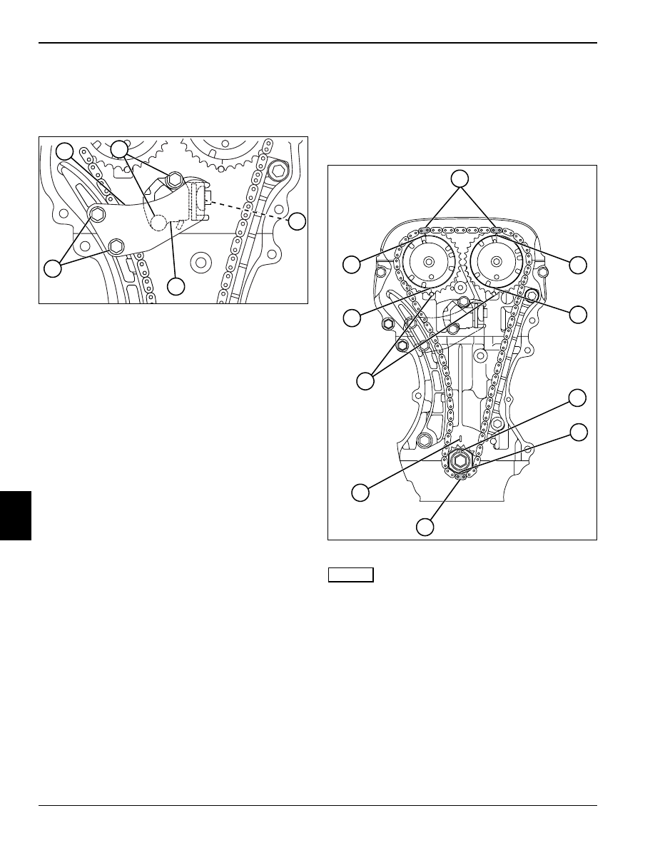
Figure 7-36
1.
Remove front cover. (See “Front Cover” on
page 7-12.)
2.
Remove cap screws (1) and tensioner link (2).
3.
Remove cap screws (3) and tension adjuster (5).
4.
Inspect tension adjuster and tensioner pad (4).
Replace as needed.
Installation Note
Install tension adjuster by reversing the order of removal.
Timing Chain
Removal
1.
Remove front cover. (See “Front Cover” on
page 7-12.)
Figure 7-37
NOTES
The crankshaft may need to be rotated several times
before cylinder number one reaches top dead center.
All timing index marks must be aligned simultaneously.
2.
Turn the crankshaft and satisfy the following
conditions to bring number one cylinder to top dead
center.
• Blue timing chain links (2) align with slot/arrow (1) on
cam timing gears.
• Cam timing gear dots (3) align with index marks (8)
on cylinder head.
• Crankshaft timing sprocket keyway (4) faces up and
aligns with index mark (7) on cylinder block.
• Yellow timing chain link (6) aligns with crankshaft
timing gear slot (5).
TN0549
1
2
3
5
4
TN0502
2
1
1
3
3
8
7
5
6
4
REPAIR
7-15
7
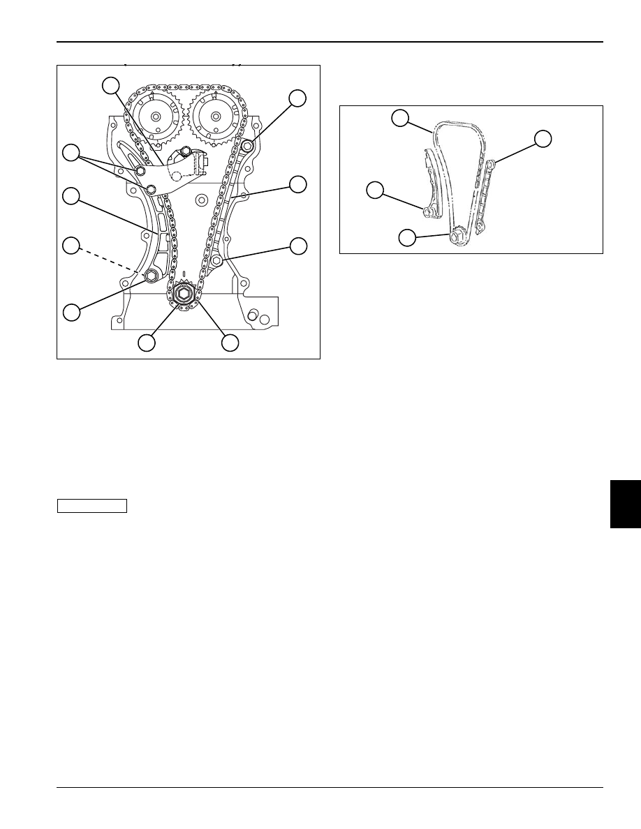
Figure 7-38
3.
Remove cap screws (9) and tensioner link (10).
4.
Remove cap screw (16), spacer (17), and
tensioner (18).
5.
Remove cap screws (11 and 13) and
chain guide (12).
6.
Slide crankshaft timing sprocket (15) and timing
chain (14) off of crankshaft. Remove timing chain
from cam gear teeth.
IMPORTANT
Do not turn camshafts or crankshaft with timing
chain removed.
Inspection
Figure 7-39
Inspect timing chain (1), chain guide (2), crankshaft
timing sprocket (3), and tensioner (4) for wear or
damage. Replace as needed.
TN0550
9
10
11
12
13
16
17
15
18
14
TN0375
1
2
3
4
7-16
REPAIR
7
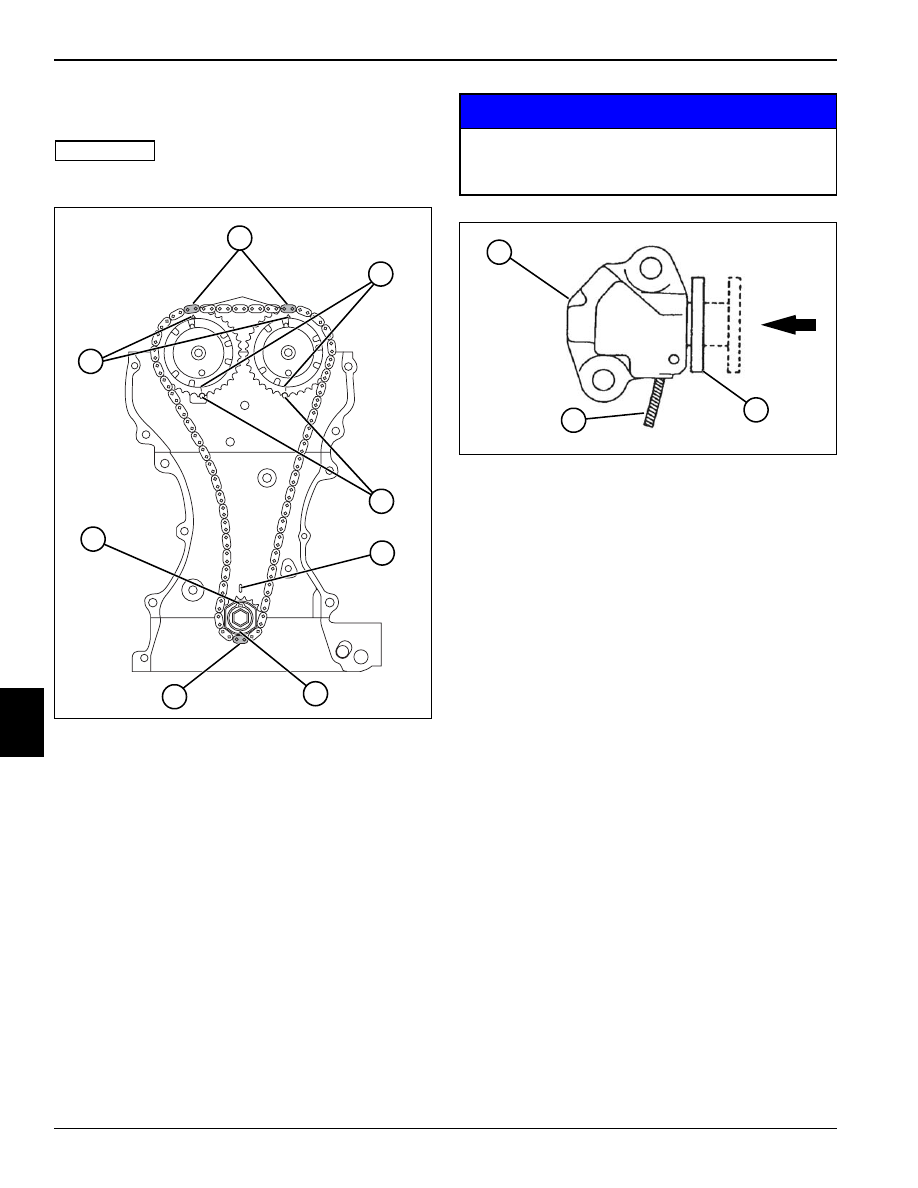
Installation
See Figures 7-40 through 7-42.
IMPORTANT
Make sure cylinder number 1 is at top dead center.
Figure 7-40
1.
Align blue timing chain links (2) with slot/arrow (1) on
cam timing gears.
2.
Align cam timing gear dots (3) with index marks (4)
on cylinder head.
3.
Be sure crankshaft timing sprocket keyway (8) faces
up and aligns with index mark (5) on cylinder block.
4.
Align yellow timing chain link (7) with crankshaft
timing gear slot (6) and slide timing gear onto
crankshaft.
NOTICE
Figure 7-41
5.
Release tension adjuster (9) manual lock using a rod
(11) approximately 0.8 in. (2 mm) in diameter.
Depress the lock with the rod and reset the piston
(10) as shown.
TN0378
2
1
3
4
5
8
6
7
Be sure to re-check timing mark(s) alignment.
Improper installation may result in engine
damage.
TN0380
10
11
9

REPAIR
7-17
7
Figure 7-42
NOTE
Apply engine oil to timing chain, tensioner, and guide
faces.
6.
Apply oil to the timing chain guide (15) and secure
using cap screws (14 and 16).
7.
Install tensioner (19) with spacer (18) and cap screw
(17).
8.
Install tensioner link (13) using cap screws (12).
9.
Install front cover. (See “Front Cover” on page 7-12.)
7.6 Cylinder Head, Cams, and
Valve Train
Cam Cover
Removal
Figure 7-43
1.
Remove ignition coils. (See “Ignition Coils” on
page 7-8.)
2.
Remove spark plugs. (See “Spark Plugs” on
page 7-8.)
3.
Remove PCV valve. (See “PCV Valve” on page 7-4.)
4.
Remove six cap screws (1) and cam cover (2).
5.
Inspect and replace as needed.
TN0550
12
13
14
15
16
17
18
19
TN0724
1
1
2
Нет комментариевНе стесняйтесь поделиться с нами вашим ценным мнением.
Текст