Suzuki: Engine K6A-YH6. Manual — part 17
7-22
REPAIR
7
Tappets and Shims
Figure 7-55
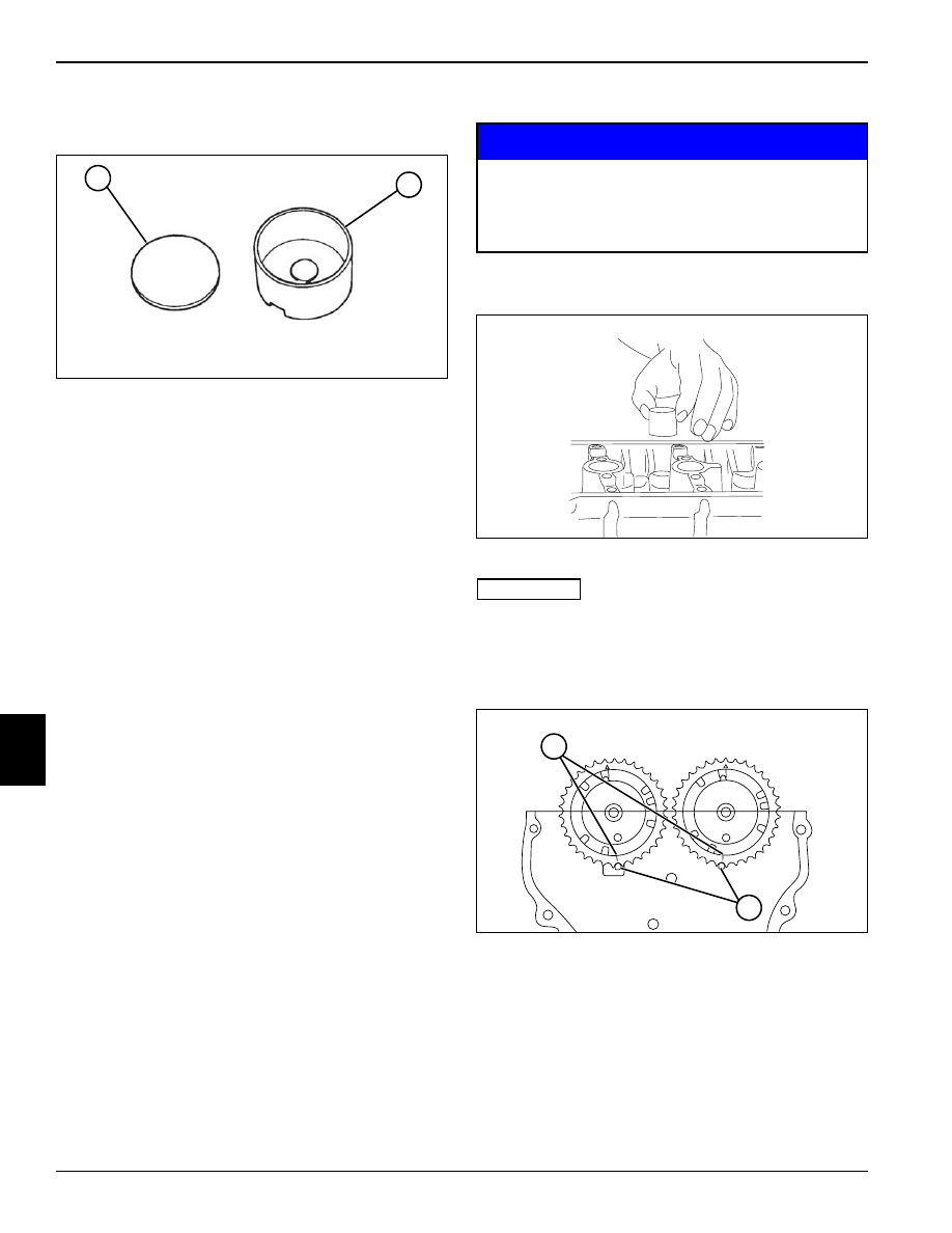
1.
Inspect shim (1) and tappet (2) for any signs of wear.
If any abnormal condition is found, replace as
needed.
2.
Measure tappet outside diameter and tappet bore
inside diameter. Calculate clearance and compare to
specification. Replace as needed.
Tappet and Bore Clearance: 0.0009—0.0024 in.
(0.025—0.062 mm)
Tappet and Bore Clearance Limit: 0.003 in.
(0.10 mm)
Installation
NOTICE
See Figures 7-56 through 7-59.
Figure 7-56
IMPORTANT
Be sure tappets and shims are installed in correct
location.
1.
Apply engine oil to all surfaces of tappets and shims,
and install in proper locations.
Figure 7-57
2.
Apply engine oil to camshaft journals, lobes, and
timing sprockets. Align timing gear dots (1) with the
index marks (2) on the cylinder head.
TN0412
1
2
Be sure to install tappets, shims, camshafts, and
camshaft housings at proper locations.
Failure to install parts properly can result in
engine damage and failure.
TN0414
TN0415
1
2
REPAIR
7-23
7
Figure 7-58
IMPORTANT
Be sure camshaft housings are properly located.
Be sure dowel pins are properly aligned before
installing camshaft housings.
3.
Check that the camshaft housing markings (3, 4, and
6) are located properly.
• The “I” or “E” markings (3) refer to intake or exhaust
side camshaft.
• The numerical markings (4) refer to the cylinder the
housing corresponds with. The cylinders are
numbered 1—3, starting from the timing chain
moving toward the rear of engine.
• The arrow marking (6) points toward the timing chain
(front of engine).
4.
Apply engine oil to cap screws and hand tighten the
camshaft housings (5) to the cylinder head.
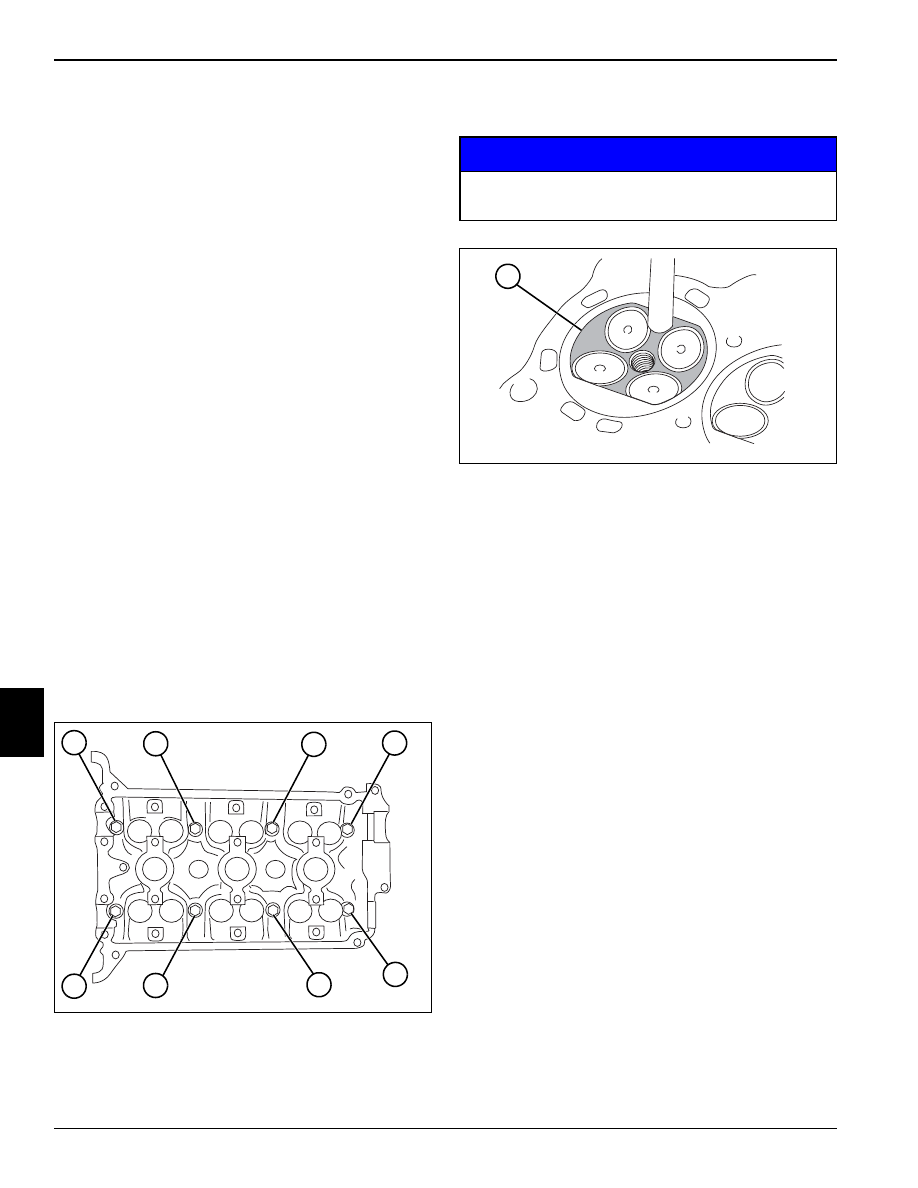
Figure 7-59
5.
Tighten camshaft housings, using sequence
(1 through 11) at increments of 32 lb-in. (3.6 N•m)
until specification is reached.
Camshaft Housing Torque: 97 lb-in. (11 N•m)
6.
Check valve clearance. (See “Valve Clearance Check
and Adjustment” on page 5-3.)
7.
Install timing chain. (See “Timing Chain” on
page 7-14.)
8.
Install front cover. (See “Front Cover” on page 7-12.)
9.
Install oil pan. (See “Oil Pan” on page 7-30.)
10. Install idler pulley. (See “Idler Pulley” on page 7-38.)
11. Install crankshaft pulley. (See “Crankshaft Pulley” on
12. Install cam cover. (See “Cam Cover” on page 7-17.)
13. Install PCV valve. (See “PCV Valve” on page 7-4.)
14. Install spark plugs. (See “Spark Plugs” on page 7-8.)
15. Install ignition coils. (See “Ignition Coils” on
TN0416
4
5
6
3
TN0409
11
10
9
8
7
6
5
4
3
2
1
7-24
REPAIR
7
Cylinder Head
Removal
1.
Remove throttle body. (See “Throttle Body” on
page 7-4.)
2.
Remove fuel rail and injectors. (See “Injectors” on
page 7-9.)
3.
Remove intake manifold. (See “Intake Manifold” on
page 7-4.)
4.
Remove exhaust manifold. (See “Exhaust Manifold”
on page 7-7.)
5.
Remove ignition coils. (See “Ignition Coils” on
page 7-8.)
6.
Remove spark plugs. (See “Spark Plugs” on
page 7-8.)
7.
Remove PCV valve. (See “PCV Valve” on page 7-4.)
8.
Remove cam cover. (See “Cam Cover” on
page 7-17.)
9.
Remove crankshaft pulley. (See “Crankshaft Pulley”
on page 7-37.)
10. Remove idler pulley. (See “Idler Pulley” on
11. Remove oil pan. (See “Oil Pan” on page 7-30.)
12. Remove front cover. (See “Front Cover” on
13. Remove timing chain. (See “Timing Chain” on
14. Remove camshafts and tappets. (See “Camshafts”
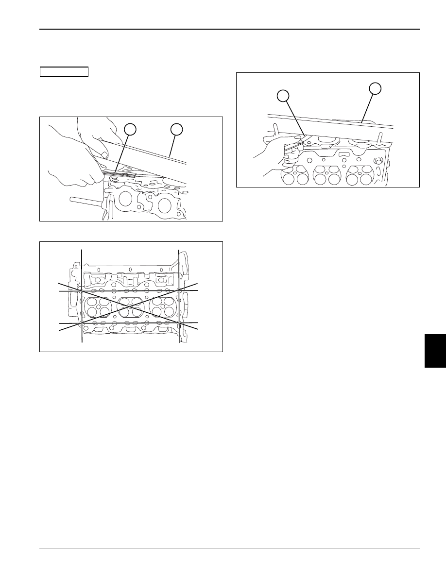
Figure 7-60
15. Loosen cap screws (1 through 8) sequentially as
shown, and remove cylinder head and gasket.
Inspection
NOTICE
Figure 7-61
Remove carbon deposits from the combustion chamber
(1). Check the intake port, exhaust port, combustion
chamber and entire cylinder head mating surface for
cracks.
TN0403
1
2
3
4
5
6
7
8
Do not scratch cylinder head surface when
removing carbon deposits.
TN0404
1
REPAIR
7-25
7
Cylinder Block Mating Face Distortion
IMPORTANT
A distorted cylinder head may cause combustion gas to
leak through the head gasket, resulting in overheating
and reduced power.
Figure 7-62
Figure 7-63
Using a straightedge (2) and a feeler gauge (1), inspect
the mating face for distortion. Place the straightedge
across bolt hole centers at the locations indicated.
Measure any gaps with the feeler gauge. If the
measurement exceeds the limit, repair or replace the
cylinder head.
Cylinder Block/Head Mating Face Distortion Limit:
0.001 in. (0.03 mm)
Intake and Exhaust Manifold Mating Face Distortion
Figure 7-64
Using a straightedge (2) and a feeler gauge (1), inspect
the manifold mating faces for distortion. Place the
straightedge across the mating face, and measure any
gaps with the feeler gauge. If the measurement exceeds
the limit, repair or replace the cylinder head.
Intake and Exhaust Manifold Mating Face Distortion
Limit: 0.000—0.002 in. (0.00—0.05 mm)
TN0405
1
2
TN0406
TN0407
1
2
Нет комментариевНе стесняйтесь поделиться с нами вашим ценным мнением.
Текст