Suzuki Grand Vitara JB416 / JB420. Manual — part 131
1H-3 Ignition System:
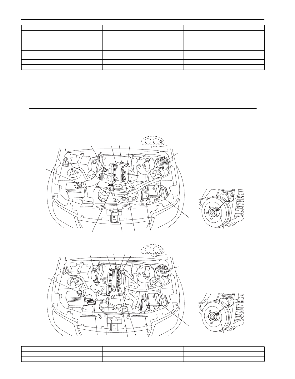
Component Location
Ignition System Components Location
S5JB0A1803001
NOTE
The figure shows left-hand steering vehicle. For right-hand steering vehicle, parts with (*) are installed
at the opposite side.
2. Main relay
10. No.4 spark plug
18. Ignition coil assembly for No.1
3. Ignition coil assembly for No.1 and No.4 spark
plugs
11. Sensed information (MAP sensor, ECT
sensor, MAF and IAT sensor, TP sensor,
Knock sensor, wheel speed signal (ABS),
Electric load signal, Engine start signal,
Torque reduction signal (TCM))
19. Ignition coil assembly for No.2
4. Ignition coil assembly for No.2 and No.3 spark
plugs
12. ECM
20. Ignition coil assembly for No.3
5. CMP sensor
13. Fuse box No.2
21. Ignition coil assembly for No.4
6. CKP sensor
14. “IGN” fuse
1
1
2
3
4
5
6
7
8
9
10
11
12*
14*
13
13
15
16
17
18
4
5
6
7
8
9
11
12*
14*
[A]
[B]
19
19
I5JB0A180002-03
[A]: For M16 engine
7. ECT sensor
15. Ignition coil assembly for No.1 (for J20 engine)
[B]: For J20 engine
8. MAF and IAT sensor
16. Ignition coil assembly for No.2 (for J20 engine)
1. ECM
9. Electric throttle body assembly
17. Ignition coil assembly for No.3 (for J20 engine)
Ignition System: 1H-4
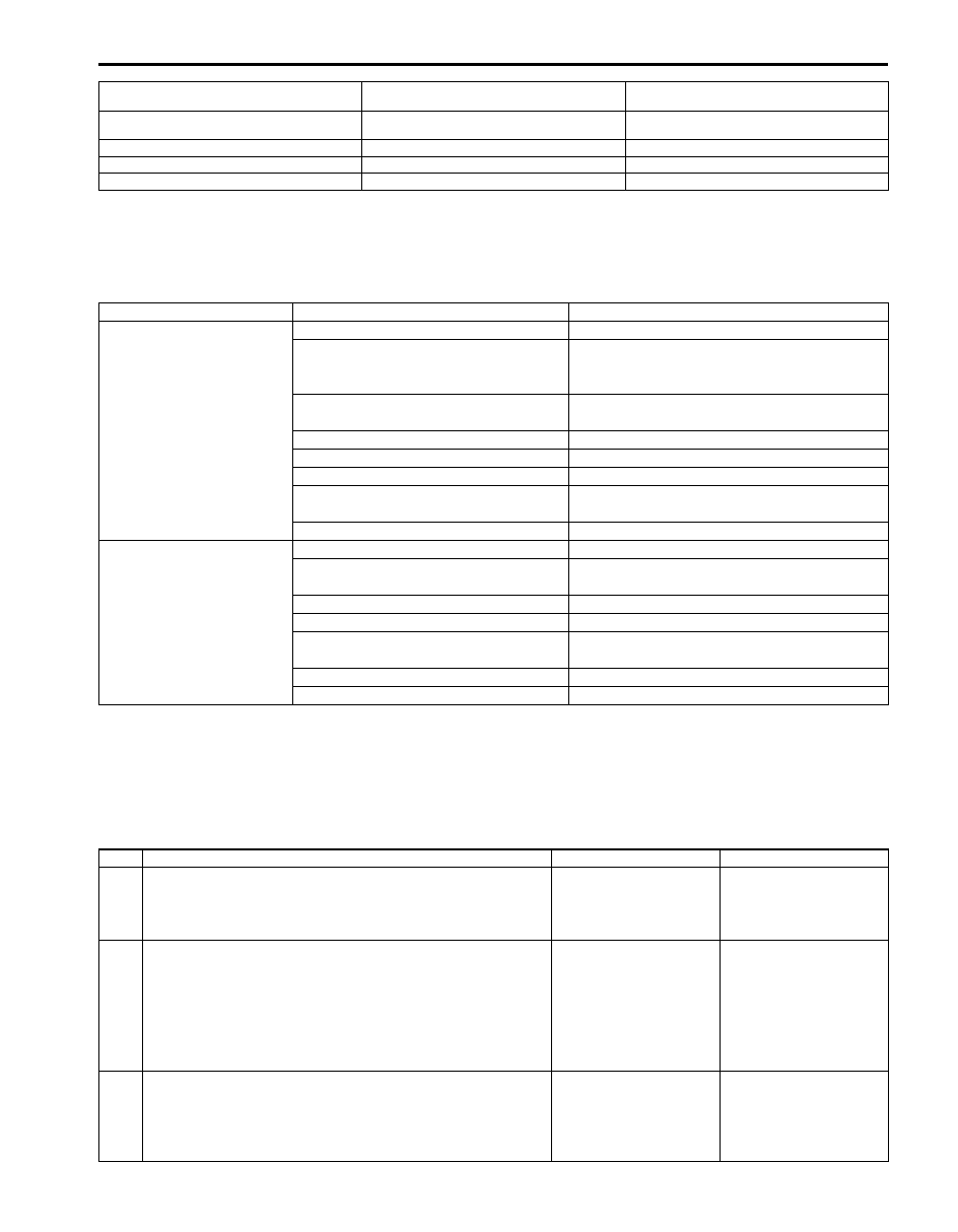
Diagnostic Information and Procedures
Ignition System Symptom Diagnosis
S5JB0A1804001
Reference Waveform of Ignition System
S5JB0A1804002
Refer to “Reference waveform No.12 to 16” and “Reference waveform No.20 and 21” under “Inspection of ECM and
Its Circuits in Section 1A” for waveform of Ignition trigger signal.
Ignition System Check
S5JB0A1804003
2. Ignition coil assembly for No.1 and No.4 spark
plugs (for M16 engine)
10. High-tension cords (for M16 engine)
18. Ignition coil assembly for No.4 (for J20 engine)
3. Ignition coil assembly for No.2 and No.3 spark
plugs (for M16 engine)
11. Knock sensor
19. ABS control module
4. CMP sensor
12. Data link connector
5. CKP sensor
13. Rear wheel speed sensor (RH, LH) (VSS)
6. MAP sensor
14. Fuse box No.2
Condition
Possible cause
Correction / Reference Item
Engine cranks, but will
not start or hard to start
(No spark)
Blown fuse for ignition coil
Replace.
Loose connection or disconnection of
high-tension cord(s) (for M16 engine) or
lead wire
Connect securely.
Faulty high-tension cord(s) (for M16
engine)
Replace.
Faulty spark plug(s)
Replace.
Faulty ignition coil
Replace ignition coil assembly.
Faulty CKP sensor or CKP sensor plate Clean, tighten or replace.
Faulty CMP sensor or sensor rotor tooth
of camshaft
Clean, tighten or replace.
Faulty ECM
Replace.
Poor fuel economy or
engine performance
Incorrect ignition timing
Check related sensors and CKP sensor plate.
Faulty spark plug(s) or high-tension
cord(s) (for M16 engine)
Adjust, clean or replace.
Faulty ignition coil assembly
Replace.
Faulty CKP sensor or CKP sensor plate Clean, tighten or replace.
Faulty CMP sensor or sensor rotor tooth
of camshaft
Clean, tighten or replace.
Faulty knock sensor
Replace.
Faulty ECM
Replace.
Step
Action
Yes
No
1
Was “Engine and Emission Control System Check”
performed?
Go to Step 2.
Go to “Engine and
Emission Control
System Check in
Section 1A”.
2
Ignition spark test
1) Check all spark plugs for condition and type referring to
2) If OK, perform ignition spark test referring to “Ignition
Is spark emitted from all spark plugs?
Go to Step 12.
Go to Step 3.
3
DTC check
1) Perform DTC check referring to “DTC Check in Section
Is DTC stored in ECM?
Go to applicable DTC
diag. flow.
Go to Step 4.

1H-5 Ignition System:
4
Electrical connection check
1) Check ignition coil assemblies and high-tension cords
(for M16 engine) for electrical connection.
Are they connected securely?
Go to Step 5 for M16
engine or go to Step 6
for J20 engine.
Connect securely.
5
High-tension cords check (for M16 engine)
1) Check high-tension cord for resistance referring to
“High-Tension Cord Inspection (For M16 Engine)”.
Is check result satisfactory?
Go to Step 6.
Replace high-tension
cord(s).
6
Ignition coil assembly power supply and ground circuit
check
1) Check ignition coil assembly power supply and ground
circuits for open and short.
Are circuits in good condition?
Go to Step 7.
Repair or replace.
7
Ignition coil assembly check
1) Check ignition coil for resistance referring to “Ignition
Coil Assembly (Including ignitor) Inspection”.
Is check result satisfactory?
Go to Step 8.
Replace ignition coil
assembly.
8
CKP sensor check
1) Check CKP sensor referring to “Crankshaft Position
(CKP) Sensor Inspection in Section 1C”.
Is check result satisfactory?
Go to Step 9.
Tighten CKP sensor
bolt, replace CKP
sensor or CKP sensor
plate.
9
CMP sensor check
1) Check CMP sensor referring to “Camshaft Position
(CMP) Sensor Inspection in Section 1C”.
Is check result satisfactory?
Go to Step 10.
Tighten CMP sensor
bolt, replace CMP
sensor or intake
camshaft.
10 Ignition trigger signal circuit check
1) Check ignition trigger signal wire for open, short and
poor connection.
Is circuit in good condition?
Go to Step 11.
Repair or replace.
11 A known-good ignition coil assembly substitution
1) Substitute a known-good ignition coil assembly and then
repeat Step 2.
Is check result of Step 2 satisfactory?
Go to Step 12.
Substitute a known-
good ECM and then
repeat Step 2.
12 Ignition timing check
1) Check initial ignition timing and ignition timing advance
referring to “Ignition Timing Inspection”.
Is check result satisfactory?
System is in good
condition.
Go to Step 13.
13 Knock sensor check
1) Confirm that knock sensor circuit is in good condition
referring to “DTC P0327 / P0328: Knock Sensor Circuit
Low / High in Section 1A”.
2) Check oscilloscope waveform of knock sensor signal
referring to “Reference waveform No.26” and
“Reference waveform No.27” under “Inspection of ECM
and Its Circuits in Section 1A”.
Is check result satisfactory?
Check CMP sensor,
CMP sensor rotor tooth
of camshaft, CKP
sensor, CKP sensor
plate and/or input
signals related to this
system.
Substitute a known-
good knock sensor and
recheck.
Step
Action
Yes
No
Ignition System: 1H-6
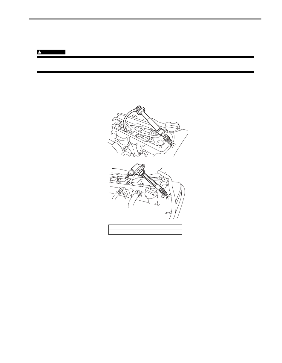
Ignition Spark Test
S5JB0A1804004
1) Remove engine cover.
2) Disconnect all injector couplers from injectors.
WARNING
!
Without disconnection of injector couplers, combustible gas may come out from spark plug holes
during this test and may get ignited in engine room.
3) Remove spark plug and check it for condition and type referring to “Spark Plug Inspection”.
4) If OK, connect ignition coil coupler to ignition coil assembly and connect spark plug to ignition coil assembly or
high-tension cord. Ground spark plug.
5) Crank engine and check if each spark plug sparks.
6) If no spark is emitted, inspect the related parts as described in “Ignition System Symptom Diagnosis”.
[A]: M16 engine model
[B]: J20 engine model
[A]
[B]
I5JB0A180003-01
Нет комментариевНе стесняйтесь поделиться с нами вашим ценным мнением.
Текст