Suzuki Grand Vitara JB416 / JB420. Manual — part 130
1G-22 Fuel System:
Specifications
Tightening Torque Specifications
S5JB0A1707001
NOTE
The specified tightening torque is also described in the following.
“Fuel System Components”
“Fuel Hose Disconnecting and Reconnecting”
Reference:
For the tightening torque of fastener not specified in this section, refer to “Fastener Information in Section 0A”.
Special Tools and Equipment
Recommended Service Material
S5JB0A1708001
NOTE
Required service material is also described in the following.
“Fuel System Components”
Fastening part
Tightening torque
Note
N
⋅m
kgf-m
lb-ft
Fuel delivery pipe bolt
25
2.5
18.0
Fuel pressure regulator bolt
11
1.1
8.0
Fuel tank bolt
50
5.0
36.5
Fuel filler hose clamp
2
0.2
1.5
Fuel pump assembly bolt
11
1.1
8.0
Material
SUZUKI recommended product or Specification
Note
Oil
SUZUKI DI O RING OIL(500CC)
P/No.: 99000–25320
Fuel System: 1G-23
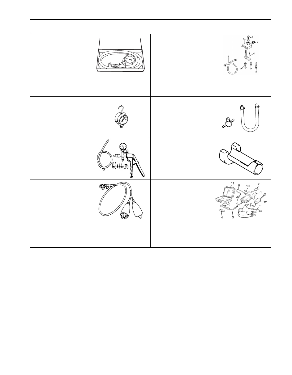
Special Tool
S5JB0A1708002
09912–58413
09912–58421
Fuel pressure gauge set
Checking tool set
This kit includes the
following items. 1. Tool body
and washer, 2. Body plug, 3.
Body attachment-1, 4.
Holder, 5. Return hose and
clamp, 6. Body attachment-2
and washer, 7. Hose
attachment-1, 8. Hose
attachment-2 )
09912–58442
09912–58490
Fuel pressure gauge
3-way joint & hose
This tool is included in fuel
pressure gauge set (09912-
58413). )
09917–47011
09919–47020
Vacuum pump gauge
Quick joint remover
09930–88530
SUZUKI scan tool
Injector test lead
—
This kit includes following
items. 1. Tech 2, 2. PCMCIA
card, 3. DLC cable, 4. SAE
16/19 adapter, 5. Cigarette
cable, 6. DLC loop back
adapter, 7. Battery power
cable, 8. RS232 cable, 9.
RS232 adapter, 10. RS232
loop back connector, 11.
Storage case, 12. )

1H-1 Ignition System:
Engine
Ignition System
General Description
Ignition System Construction
S5JB0A1801001
The ignition system is an electronic (distributor less)
ignition system. Especially a direct ignition system is
adopted for J20 engine. They consists of the parts as
described below.
• ECM
It detects the engine and vehicle conditions through
the signals from the sensors, determines the most
suitable ignition timing and time for electricity to flow
to the primary coil and sends a signal to the ignitor
(power unit) in the ignition coil assembly.
• Ignition coil assembly (including an ignitor and an
ignition coil)
The ignition coil assembly has a built-in ignitor which
turns ON and OFF the current flow to the primary coil
according to the signal from ECM. When the current
flow to the primary coil is turned OFF, a high voltage is
induced in the secondary coil.
• High-tension cords (for M16 engine) and spark
plugs
• CMP sensor (Camshaft position sensor) and CKP
sensor (Crankshaft position sensor)
Using signals from these sensors, ECM identifies the
specific cylinder whose piston is in the compression
stroke, detects the crank angle and adjusts initial
ignition timing automatically.
• TP sensor, ECT sensor, MAP sensor, MAF sensor,
IAT sensor, knock sensor, wheel speed sensor
(VSS) and other sensors / switches
For M16 engine, this ignition system does not have a
distributor, it has two ignition coil assemblies (one is for
No.1 and No.4 spark plugs and the other is for No.2 and
No.3 spark plugs). When an ignition signal is sent from
ECM to the ignitor in the ignition coil assembly for No.1
and No.4 spark plugs, a high voltage is induced in the
secondary coil and that passes through the high-tension
cords and causes No.1 and No.4 spark plugs to spark
simultaneously. Likewise, when an ignition signal is sent
to the ignitor in the other ignition coil assembly, No.2 and
No.3 spark plugs spark simultaneously.
For J20 engine, although ignition system does not have
a distributor and high-tension cords but each cylinder
has an ignition coil assembly (ignitor and ignition coil)
and the secondary voltage which occurred in the ignition
coil is sent to the spark plug directly. Also, the signal (s)
are sent from the CMP sensor to ECM so as to control
each ignition coil independently through the ignitor (in
ignition coil assembly).

Ignition System: 1H-2
Schematic and Routing Diagram
Ignition System Wiring Circuit Diagram
S5JB0A1802001
E23
C37
3
4
18
19
5
6
7
10
11
17
20
47
46
49
50
51
21
22
52
16
25
9
24
14
29
55
57
54 53
59
60
58
2
26
27
28
15
30
56
48
32
31
34
35
36
37
40
42
39 38
44
45
43
41
33
1
12
13
23
8
3
4
18
19
5
6
7
10
11
17
20
47
46
49
50
51
21
22
52
16
25
9
24
14
29
55
57
54 53
59
60
58
2
26
27
28
15
30
56
48
32
31
34
35
36
37
40
42
39 38
44
45
43
41
33
1
12
13
23
8
E23-60
E23-29
12V
5V
E23-1
E23-16
BLK/WHT
BLU/BLK
BLU/BLK
BLU/BLK
BLK/RED
BLK/RED
BLK/RED
BLK/YEL
WHT/GRN
BLK
BLU
BLK/ORN
1
2
11
C37-15
C37-29
C37-48
13
14
15
16
17
5
6
BLK/YEL
C37-51
5V
5V
C37-52
WHT/RED
WHT/BLU
5V
5V
BLK/WHT
BLK/WHT
BRN/BLK
BRN
C37-20
C37-21
BLK/ORN
BLK/ORN
C37-30
BLK/ORN
BLK/YEL
BLK/YEL
BLK/YEL
C37-58
[A]
[B]
3
4
7
8
9
10
12
E23-60
E23-29
12V
5V
E23-1
E23-16
BLK/WHT
BLU/BLK
BLU/BLK
BLU/BLK
BLK/RED
BLK/RED
BLK/RED
BLK/YEL
WHT/GRN
BLU
BLK/ORN
1
2
11
C37-15
C37-29
C37-48
13
14
15
16
17
5
6
BLK/YEL
5V
C37-52
WHT/RED
5V
5V
BLK/WHT
BRN/BLK
BRN
C37-20
C37-21
5V
5V
BLK/WHT
BRN/YEL
BRN/WHT
C37-18
C37-19
BLK/ORN
BLK/ORN
BLK/ORN
BLK/ORN
C37-30
BLK/ORN
BLK/YEL
BLK/YEL
BLK/YEL
C37-58
C37-51
C37-36
BLU
PNK
BLK
7
8
9
10
18
20
19
21
12
BLK
I5JB0A180001-02
[A]: For M16 engine
7. No.1 spark plug
15. “FI” fuse
[B]: For J20 engine
8. No.2 spark plug
16. Junction block
1. Ignition switch
9. No.3 spark plug
17. “IG COIL” fuse
Нет комментариевНе стесняйтесь поделиться с нами вашим ценным мнением.
Текст