Suzuki Grand Vitara JB416 / JB420. Manual — part 78
1B-3 Aux. Emission Control Devices:
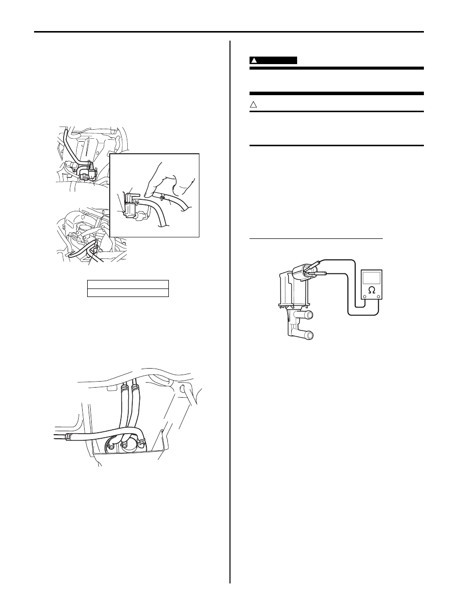
Vacuum Passage Inspection
S5JB0A1206003
Start engine and run it at idle speed. Disconnect vacuum
hose (1) from EVAP canister purge valve (2). With finger
placed against disconnected hose, check that vacuum is
applied.
If it is not applied, clean vacuum passage by blowing
compressed air.
Vacuum Hose and Purge Valve Chamber
Inspection
S5JB0A1206004
Check hoses and purge valve chamber for connection,
leakage, clog and deterioration.
Replace as necessary.
EVAP Canister Purge Valve Inspection
S5JB0A1206005
WARNING
!
Do not apply vacuum by mouth; otherwise
harmful fuel vapor can be breathed in.
CAUTION
!
Do not apply vacuum more than –86 kPa (–
12.47 psi); otherwise EVAP canister purge
valve could be damaged.
1) With ignition switch turned OFF, disconnect coupler
and vacuum hoses from canister purge valve.
2) Remove EVAP canister purge valve from intake
manifold.
3) Check resistance between two terminals of EVAP
canister purge valve.
If resistance is not as specified, replace EVAP
canister purge valve.
EVAP canister purge valve resistance
30 – 34
Ω at 20 °C (68 °F)
[A]: For J20 engine
[B]: For M16 engine
[B]
[A]
2
2
1
2
I5JB0A120006-01
I5JB0A120007-01
I3RM0A120008-01

Aux. Emission Control Devices: 1B-4
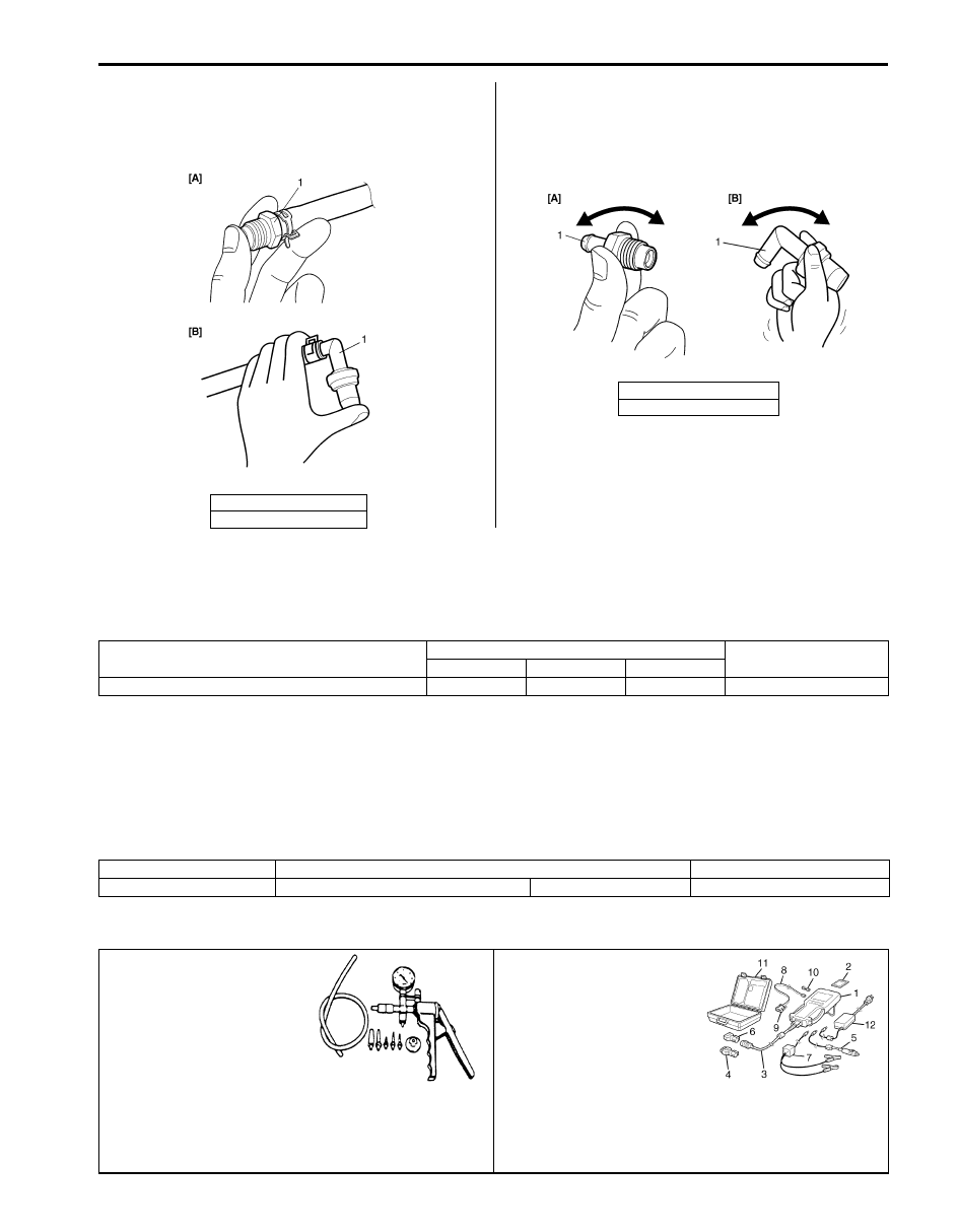
4) With coupler disconnected, apply vacuum (–60 kPa
(–8.7 psi)) to pipe (1). If vacuum can be applied, go
to next step. If vacuum can not be applied, replace
EVAP canister purge valve.
5) In this state, connect 12 V-battery to EVAP canister
purge valve terminals. If vacuum can not be applied,
EVAP canister purge valve is in good condition.
If applied, replace EVAP canister purge valve.
WARNING
!
Do not suck the air through valve. Fuel vapor
inside valve is harmful.
Special tool
(A): 09917–47011
6) Install EVAP canister purge valve to intake manifold.
EVAP Canister Inspection
S5JB0A1206006
WARNING
!
Do not suck nozzles on EVAP canister. Fuel
vapor inside EVAP canister is harmful.
1) Check outside of EVAP canister visually.
2) Disconnect vacuum hoses from EVAP canister.
3) Check that there is no restriction of flow through
purge pipe (1) and air pipe (2) when air is blown (4)
into tank pipe (3).
If any faulty condition is found in this inspection,
replace EVAP canister.
EGR Valve Removal and Installation
S5JB0A1206007
Removal
1) Disconnect negative cable at battery.
2) Remove EGR pipe.
3) Disconnect EGR valve connector.
4) Remove EGR valve and gasket from cylinder head.
Installation
Reverse removal procedure noting the following.
• Clean mating surface of valve and cylinder head.
• Use new gaskets.
1
1
(A)
(A)
I3RB0A120007-01
I2RH0B120001-01
1B-5 Aux. Emission Control Devices:
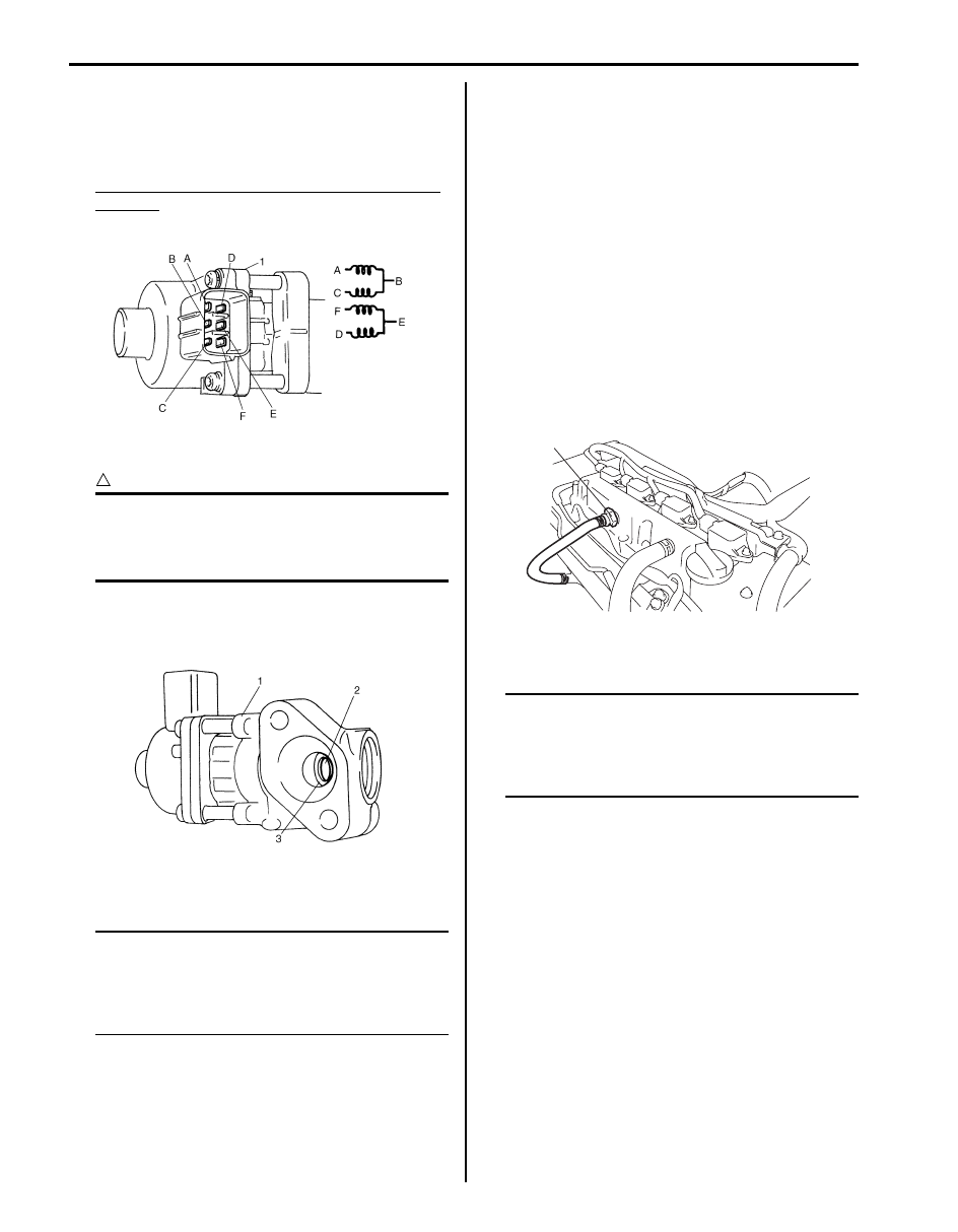
EGR Valve Inspection
S5JB0A1206008
1) Check resistance between following terminals of
EGR valve (1) in each pair.
If found faulty, replace EGR valve assembly.
EGR valve resistance (A – B, C – B, F – E, D – E
terminal)
20 – 24
Ω
2) Remove carbon from EGR valve gas passage.
CAUTION
!
Do not use any sharp-edged tool to remove
carbon.
Be careful not to damage or bend EGR valve
(1), valve seat (3) and rod.
3) Inspect valve (2), valve seat and rod for fault, cracks,
bend or other damage.
If found faulty, replace EGR valve assembly.
PCV Hose Inspection
S5JB0A1206009
NOTE
Be sure to check that there is no obstruction
in PCV valve or its hoses before checking
IAC throttle opening, for obstructed PCV
valve or hose hampers its accurate
adjustment.
Check hoses for connection, leakage, clog and
deterioration.
Replace as necessary.
PCV Valve Removal and Installation
S5JB0A1206011
Removal
1) Disconnect PCV hose from PCV valve.
2) Remove PCV valve from cylinder head cover.
Installation
Reverse removal procedure noting the following.
• For J20 engine, apply sealant to thread part of PCV
valve (1).
“A”: Water tight sealant 99000–31250 (SUZUKI
Bond No.1207F)
• For J20 engine, tighten PCV valve to specified torque.
Tightening torque
PCV valve (a): 27 N·m (2.7 kgf-m, 19.5 lb-ft)
• Connect PCV hose to PCV valve securely.
PCV Valve Inspection
S5JB0A1206010
NOTE
Be sure to check that there is no obstruction
in PCV valve or its hoses before checking
IAC throttle opening, for obstructed PCV
valve or hose hampers its accurate
adjustment.
1) Remove PCV valve referring to “PCV Valve Removal
2) Connect PCV valve to hose and install plug to
cylinder head cover hole.
3) Run engine at idle.
I2RH0B120005-01
I2RH0B120006-01
1, (a), A
I5JB0A120008-01
Aux. Emission Control Devices: 1B-6
4) Place your finger over end of PCV valve (1) to check
for vacuum.
If there is no vacuum, check for clogged valve.
Replace as necessary.
5) After checking vacuum, stop engine and remove
PCV valve (1).
Shake valve and listen for rattle of check needle
inside the valve. If valve does not rattle, replace PCV
valve.
6) After checking, remove plug and install PCV valve.
7) Install air cleaner assembly securely.
Specifications
Tightening Torque Specifications
S5JB0A1207001
Reference:
For the tightening torque of fastener not specified in this section, refer to “Fastener Information in Section 0A”.
Special Tools and Equipment
Recommended Service Material
S5JB0A1208001
Special Tool
S5JB0A1208002
[A]: For J20 engine
[B]: For M16 engine
I5JB0A120009-04
[A]: For J20 engine
[B]: For M16 engine
I5JB0A120010-03
Fastening part
Tightening torque
Note
N
⋅m
kgf-m
lb-ft
PCV valve
27
2.7
19.5
Material
SUZUKI recommended product or Specification
Note
Water tight sealant
SUZUKI Bond No.1207F
P/No.: 99000–31250
09917–47011
SUZUKI scan tool
Vacuum pump gauge
—
This kit includes following
items. 1. Tech 2, 2. PCMCIA
card, 3. DLC cable, 4. SAE
16/19 adapter, 5. Cigarette
cable, 6. DLC loop back
adapter, 7. Battery power
cable, 8. RS232 cable, 9.
RS232 adapter, 10. RS232
loop back connector, 11.
Storage case, 12. )
Нет комментариевНе стесняйтесь поделиться с нами вашим ценным мнением.
Текст