Suzuki Grand Vitara JB416 / JB420. Manual — part 77
1A-257 Engine General Information and Diagnosis:
Repair Instructions
Idle Speed and IAC Throttle Valve Opening
Inspection
S5JB0A1106001
Before idle speed check, make sure of the following.
• Lead wires and hoses of electronic fuel injection and
engine and emission control systems are connected
securely.
• Valve lash is checked according to maintenance
schedule.
• Ignition timing is within specification.
• All accessories (wipers, heater, lights, A/C, etc.) are
out of service.
• Air cleaner has been properly installed and is in good
condition.
• No abnormal air drawn in from air intake system.
After all items are confirmed, check idle speed and IAC
throttle opening as follows.
NOTE
Before starting engine, place transmission
gear shift lever in “Neutral” (shift selector
lever to “P” range for A/T vehicle), and set
parking brake and block drive wheels.
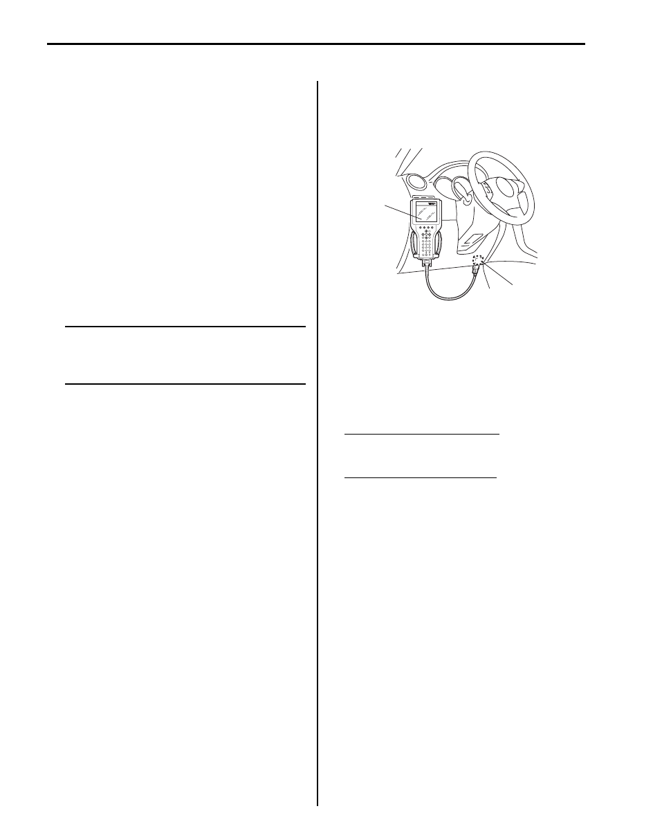
1) Connect SUZUKI scan tool to DLC (1) with ignition
switch turned OFF.
Special tool
(A): SUZUKI scan tool
2) Warm up engine to normal operating temperature.
3) Check engine idle speed and “IAC throttle opening”
by using “Data List” mode on scan tool to check “IAC
throttle opening”.
4) If check result is out of specification, inspect electric
throttle body assembly referring to “Electric Throttle
Body Assembly On-Vehicle Inspection in Section
1C”.
Engine idle speed (M16 Engine)
A/C OFF: 660
± 50 rpm (IAC duty: 5 – 55%)
A/C ON: 750
± 50 rpm
Engine idle speed (J20 Engine)
A/C OFF: 650
± 50 rpm (IAC duty: 5 – 55%)
A/C ON: 750
± 50 rpm
5) Check that specified engine idle speed is obtained
with A/C turned ON if vehicle is equipped with A/C.
If not, check A/C system.
(A)
1
I5JB0A110106-01
Engine General Information and Diagnosis: 1A-258
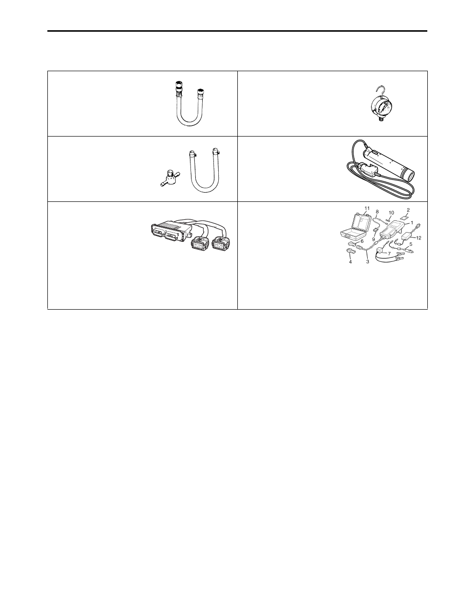
Special Tools and Equipment
Special Tool
S5JB0A1108001
09912–58432
09912–58442
Fuel pressure gauge hose
Fuel pressure gauge
This tool is included in fuel
pressure gauge set (09912-
58413). )
This tool is included in fuel
pressure gauge set (09912-
58413). )
09912–58490
09930–76420
3-way joint & hose
Timing-light (dry cell type)
09933–06320
SUZUKI scan tool
ECM check harness (120P)
—
This kit includes following
items. 1. Tech 2, 2. PCMCIA
card, 3. DLC cable, 4. SAE
16/19 adapter, 5. Cigarette
cable, 6. DLC loop back
adapter, 7. Battery power
cable, 8. RS232 cable, 9.
RS232 adapter, 10. RS232
loop back connector, 11.
Storage case, 12. ) / )

1B-1 Aux. Emission Control Devices:
Engine
Aux. Emission Control Devices
Diagnostic Information and Procedures
EGR System Inspection
S5JB0A1204001
1) Connect SUZUKI scan tool to data link connector
(DLC) with ignition switch turned OFF.
2) Turn ON ignition switch and erase DTC using
“CLEAR DTC” in “TROUBLE CODES” menu.
3) Start engine and warm it up to normal operating
temperature, then select “DATA LIST” mode on scan
tool.
4) Make sure that vehicle condition is as follows.
• Vehicle speed = 0 km/h (0 mph)
• Engine speed
≤ 900 rpm
• Engine coolant temp.
≥ 90 °C, 194 °F
5) With engine idling (without depressing accelerator
pedal), open EGR valve by using “STEP EGR” mode
in “MISC TEST” menu. In this state, as EGR valve
opening increases engine idle speed drops. If not,
possible cause is clogged EGR gas passage, stuck
or faulty EGR valve.
Repair Instructions
EVAP Canister Purge Inspection
S5JB0A1206001
NOTE
Before inspection, check to make sure that
gear shift lever is in neutral position (with A/T
model, selector lever in “P” range) and that
parking brake lever is pulled all the way up.
1) Hoist vehicle.
2) Disconnect purge hose (1) from EVAP canister (2).
3) Place finger against the end of disconnected hose
and check that vacuum is not felt there when engine
is cool and running at idle speed. If check result is
not satisfactory, check EVAP canister purge valve,
wire harness and ECM.
1. SUZUKI scan tool display
2. EGR valve opening (0: Close, 100: Full open)
Step EGR
Step EGR Flow Duty 21 %
Step EGR (con) 23%
Engine Speed 771 RPM
Desired Idle 698 RPM
IAC Flow Duty 20.0 %
Ignition Advance 11.5 BTDC
Closed Throttle Pos ON
1
2
I5JB0A120001-01
1
2
I5JB0A120002-01
Aux. Emission Control Devices: 1B-2
EVAP Canister Purge Valve and Its Circuit
Inspection
S5JB0A1206002
WARNING
!
Do not apply vacuum by mouth; otherwise
harmful fuel vapor can be breathed in.
CAUTION
!
Do not apply vacuum more than –86 kPa (–
12.47 psi); otherwise EVAP canister purge
valve could be damaged.
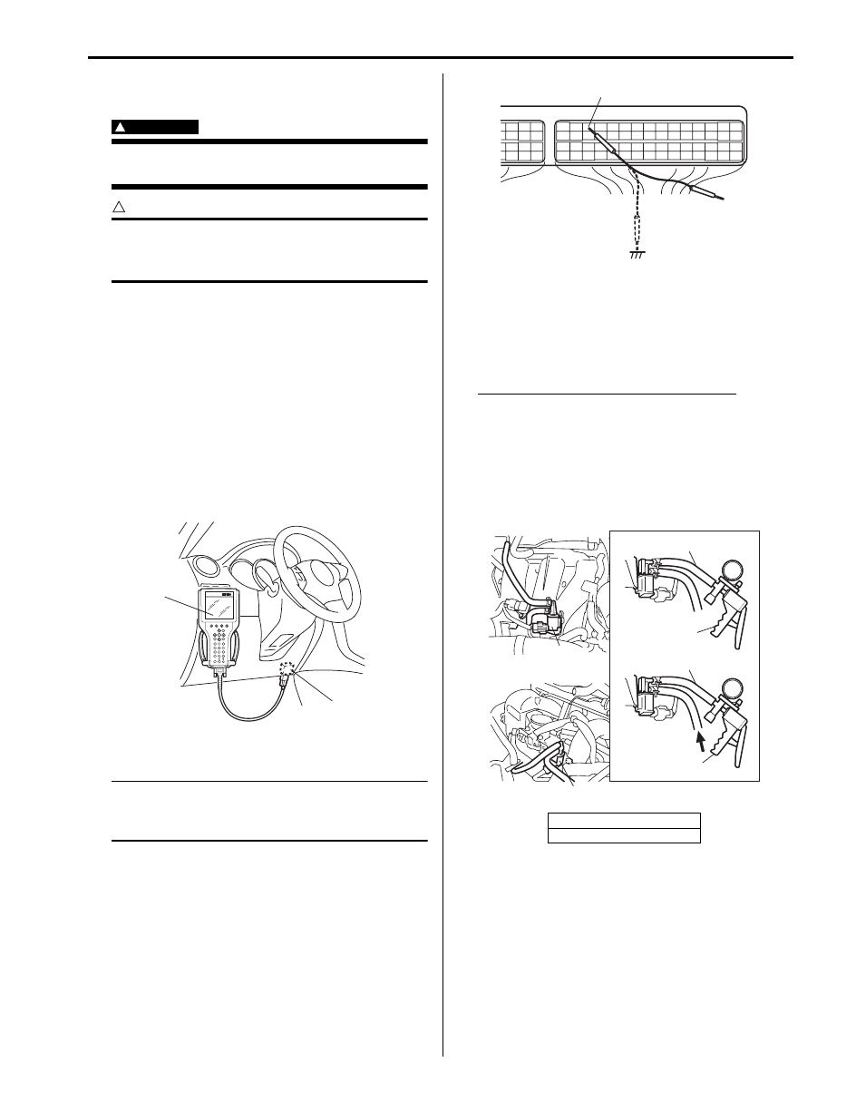
1) Prepare to operate EVAP canister purge valve as
follows.
a) When using SUZUKI scan tool:
i)
Connect SUZUKI scan tool to DLC (1) with
ignition switch turned OFF and disconnect
purge valve vacuum hoses from intake
manifold and purge pipe.
ii) Turn ON ignition switch, clear DTC and
select “MISC TEST” mode on SUZUKI scan
tool.
Special tool
(A): SUZUKI scan tool
b) When not using SUZUKI scan tool:
NOTE
Before performed this check, be sure to read
the “Precautions of ECM Circuit Inspection in
Section 1A”.
i)
Disconnect purge valve vacuum hoses from
intake manifold and purge pipe.
ii) Remove ECM cover.
iii) Connect special tool between ECM and ECM
connector referring to “Inspection of ECM
and Its Circuits in Section 1A”
iv) Turn ON ignition switch.
Using service wire, ground “C37-13” terminal
circuit of special tool (valve ON: “B”) and
unground it (valve OFF: “A”).
2) Check purge valve (2) for operation and vacuum
passage for clog when valve is switched ON and
OFF by using SUZUKI scan tool or service wire.
If check result is not satisfactory, check vacuum
hoses, EVAP canister purge valve, wire harness and
connections.
EVAP canister purge valve specification
[C] Valve OFF: When vacuum (–60 kPa (–8.7 psi))
is applied to hose (1), vacuum can be applied.
[D] Valve ON: When vacuum is applied to hose
(1), vacuum can not be applied.
Special tool
(A): 09917–47011
(A)
1
I5JB0A120003-01
[A]: For J20 engine
[B]: For M16 engine
“C37-13”
“A”
“B”
I5JB0A120004-01
[B]
[A]
[D]
[C]
(A)
1
1
2
2
(A)
I5JB0A120005-01
Нет комментариевНе стесняйтесь поделиться с нами вашим ценным мнением.
Текст